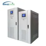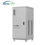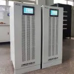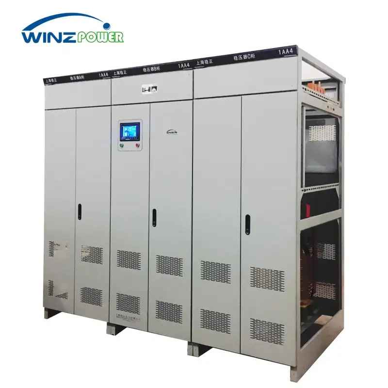
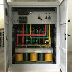
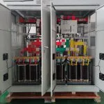
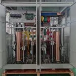
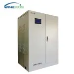
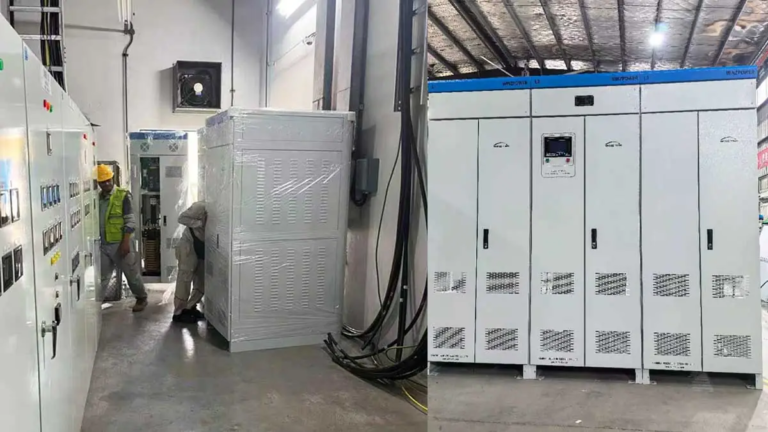
Meiji Indonesia Food Plant · 1000KVA


Independent phase regulation voltage stabilizer designed for industrial facilities with unbalanced three-phase power supply, weak grids and uneven load conditions.
Rated Power: 20-3000KVA
Input Voltage:200/220/380/400/440/480V ±20%
Input Frequency:50/60Hz ±10%
Output Voltage:200/220/380/400/440/480V ±2%
Phase Regulation:Independent Phase Adjustment
Application:Industrial Facilities & Unbalanced Power Systems
The SBW-F series is a three-phase voltage stabilizer with independent phase regulation, designed for industrial power systems where phase voltage imbalance occurs due to uneven loads, weak grids, or long-distance power distribution.
The key difference between SBW-F and conventional three-phase voltage stabilizers is the regulation method. SBW-F adjusts each phase independently, while conventional systems regulate three phases together. Independent phase regulation is designed for three-phase voltage imbalance and unbalanced power systems.
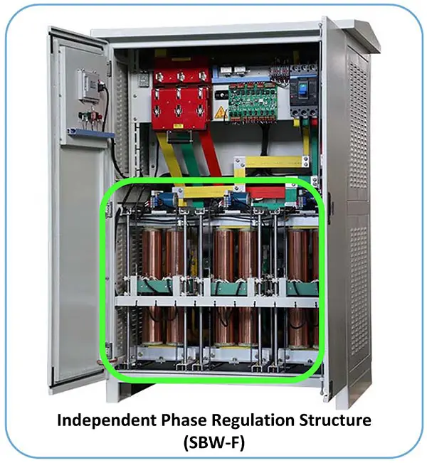
Independent Phase Regulation Structure (SBW-F)
How Independent Phase Regulation Works
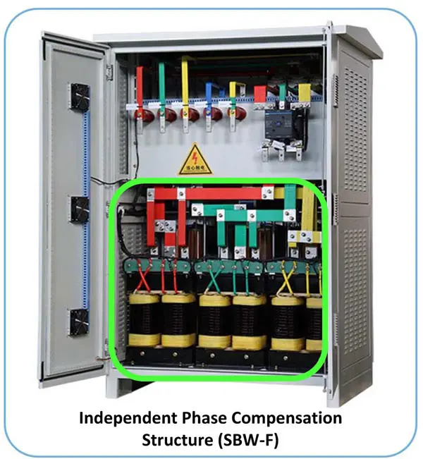
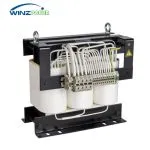
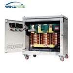
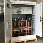
Independent Phase Compensation Transformer Structure (SBW-F)
The SBW-F series uses independent phase compensation transformer structures to achieve phase-by-phase voltage regulation. This design is suitable for large-capacity industrial applications and three-phase power systems with voltage imbalance.
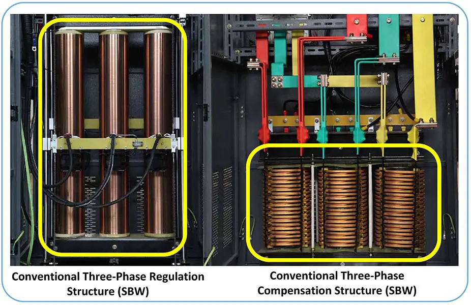
Conventional Three-Phase Common Regulation and Compensation Structure
Conventional Three-Phase Regulation Structure
The selection depends on the power system condition rather than product preference. Independent phase regulation is recommended for unbalanced three-phase power systems, while conventional three-phase regulation is suitable for general industrial voltage stabilization.
| Item | SBW-F Independent Phase Regulation | Conventional SBW Three-Phase Regulation |
| Regulation Method | Each phase regulated independently | Three phases regulated together |
| Suitable Power Conditions | Unbalanced three-phase power systems | General industrial voltage fluctuation |
| Typical Applications | Mining, large factories, weak grids, uneven loads | CNC machines, production lines, balanced industrial loads |
| Key Advantage | Independent phase voltage correction under unbalanced conditions | Reliable voltage stabilization for balanced three-phase industrial applications |
For general industrial applications where three-phase voltage balance is acceptable, Winzele also provides the SBW Three-Phase Servo Voltage Stabilizer for reliable voltage stabilization of factories, production lines and industrial equipment.
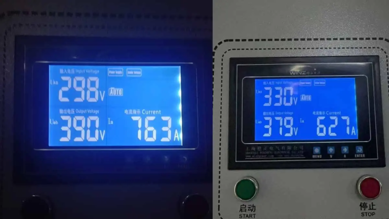
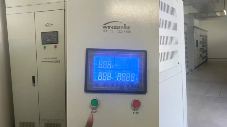
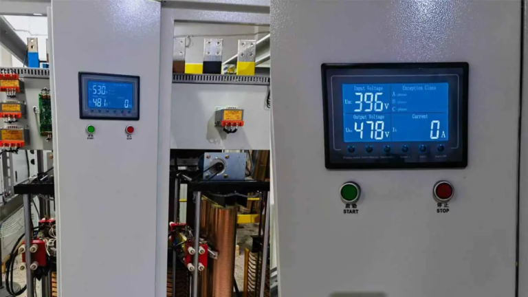
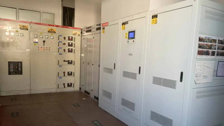
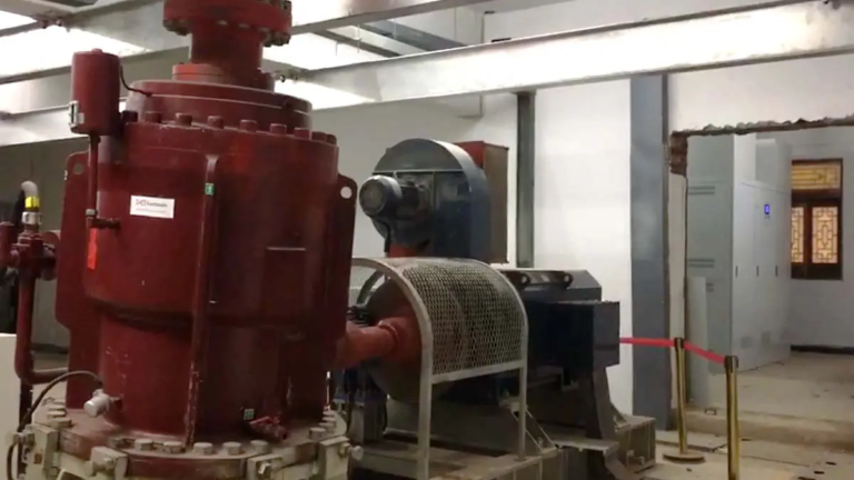
Selected installations using Winzele voltage stabilization equipment.
Looking for a similar project?
Explore more real installations by equipment, industry and capacity.
The SBW-F series stabilizes each phase of a three-phase power system independently. A voltage measuring unit monitors every phase and detects any deviation from the rated voltage, then the servo motor adjusts the regulating transformer so that the compensation transformer generates the required compensation voltage. This phase-by-phase regulation directly solves three-phase voltage imbalance caused by unbalanced grid voltage, unstable supply or uneven load changes.
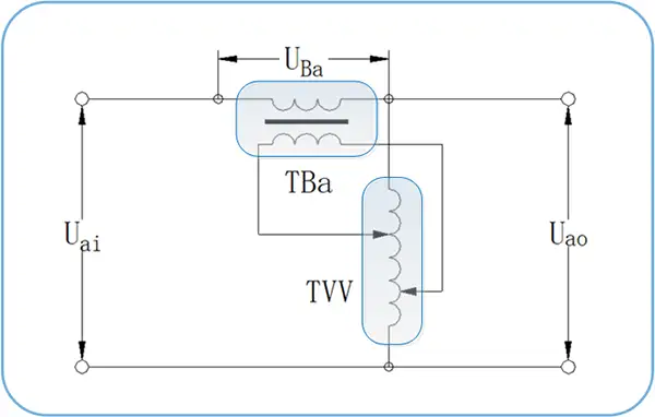
SBW-F independent phase voltage regulation compensation principle
The control and regulating voltage transformer TVV is connected in Y shape to the output end of the stabilizer, and its primary winding connects with the primary winding of the compensation transformer TBa. The secondary winding of TBa is connected in series with the main circuit. Taking phase A as an example, the output voltage is maintained by adding the compensation voltage generated by the compensation transformer to the input voltage: Uao = Uai + UBa. When the input voltage changes, the regulating transformer adjusts the compensation voltage accordingly, keeping the output voltage within the required accuracy range.
The voltage measuring unit continuously monitors output voltage variation and sends control signals to the servo motor. Through the speed reducer and brush assembly, the regulating transformer changes the compensation voltage to maintain stable output voltage automatically. Phase B and phase C are regulated in the same way.
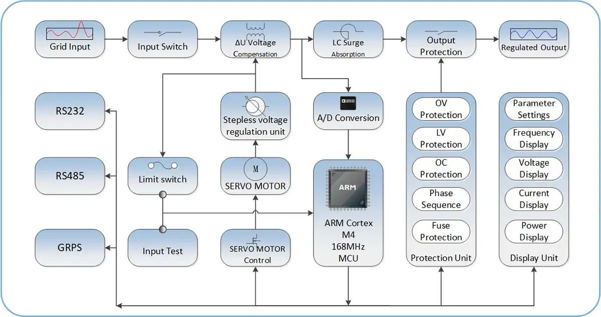
SBW-F digital control system MCU control logic
The digital control system is built around an MCU that monitors the output voltage of each phase in real time. The voltage detection unit provides continuous feedback to the control circuit, which coordinates the automatic adjustment process. Protection functions include overvoltage protection, phase loss protection and phase sequence protection, ensuring safe and reliable operation of the stabilizer and the connected equipment.
The SBW-F series is designed for industrial power systems requiring independent phase voltage regulation and stable operation under unbalanced three-phase power conditions.
Features
| Parameter | Technical Indicators | Remark |
| Rated Voltage(Vac) | Three Phase 200V/208V/220V/380V/400V/440V/480V(Any voltage can be customized) | Three phase three wire (L1, L2, L3) +N(Neutral wire)+Ground(PE). |
| Input Voltage Range(%) | (Rated Voltage)±20%.e.g.380V±20%(Customizable other voltage input ranges) | Generally, the input voltage range can be ±15%/20%/30%/40% of the rated voltage. |
| Input Frequency(Hz) | Default 50/60Hz | Other frequencies can be customized |
| Output Voltage(Vac) | Three-phase 380V/400V (±10% adjustable) | Other voltages can also be customized, e.g: Three-phase 200V/220/440V/480V or other. |
| Output Voltage Stability Accuracy | ±1-5% (2-5% for normal products) | |
| Output Frequency | Same as input frequency | |
| Efficiency | 98% | |
| Output THD Increase | <0.1%(static and dynamic) | No additional waveform distortion (static and dynamic) is generated. The voltage THD increment is less than 0.1% |
| Output isolation transformer | △/Y or Y/Y | Optional |
| Parameter | Technical Indicators | Remark |
| Voltage Regulation Mode | Each phase is independently adjustable. | |
| Dynamic Response Time | 40ms(Relative AC input voltage) | |
| Three-phase imbalance | Output three-phase voltage automatic control balance(YES) | Three-phase voltage automatic control balance(YES) |
| Applicable load type | Any load type (resistive, inductive, capacitive) | |
| Overload Capacity | 120% 10min 150% 1min | |
| Bypass Function | Manual bypass | Automatic bypass when an internal fault occurs optional |
| Parameter | Technical Indicators | Remark |
| Control Mode | Full digital control | The analog part is used for input and output signal conditioning |
| Main Control Unit | The main chip uses STM32F4XX for control and measurement | Some models use ARM master control with DSP function |
| Control Strategy | Digital Hysteresis Comparator & PID | |
| Motor Drive Mode | Thyristor driver(zero-crossing trigger) | |
| Stabilization Time | The input voltage ratings relative to the Range change of 10%, stable time less than 1 second | Load power 0-100% |
| Voltage and Current Measurement Methods | True RMS sampling (three-phase synchronization) | RMS & FFT sampling 256 points |
| Voltage & Current Control Strategy | PID double closed loop control |
| Parameter | Technical Indicators | Remark |
| Communication Interface | RS485/232/MODBUS-RTU Protocol | Optional TCP/IP, GPRS and other interfaces |
| Display Media | Multi function LCD segment code | Industrial touch screen(7″or 10″) can also be customized |
| Display Electrical Parameters |
Input three-phase voltage and frequency;Output three-phase line voltage and frequency;Output line voltage average value;Output power factor;Output three-phase current;Output active power and apparent power; |
|
| Display Alarm Information | Output overvoltage (OV), overcurrent (OC); Output undervoltage (UV); Overload;Phase sequence fault; and other fault information | |
| Display Accuracy | The accuracy is Class 0.5s | |
| Voltage Display Resolution | 0.1V | |
| Current Display Resolution | 0.1A | |
| Parameter | Technical Indicators | Remark |
| Protection List | Output overvoltage (OV), overcurrent (OC); Output undervoltage (UV); transformer overheat; and Short Circuit;Phase sequence fault | |
| Protection Action | Cut off output and alarm;Automatic bypass;Automatically start after failure recovery | Fault dry contacts can be configured(NC&NO) |
| Parameter | Technical Indicators | Remark |
| Working Temperature(℃) | -35℃ to +55℃ | Extreme temperature environments require special customization or derating |
| Relative Humidity(RH) | 10%-90%(20℃±5℃) | |
| Altitude | <2000m | For every 1000m increase in altitude, the rating should be derated by 10%. |
| IP Class | IP20 | Other IP Classes such as outdoor IP33 can be customized |
| Noise Level(dB) | <55dB |
Other special requirements can be communicated with winzele
| Type | Rated capacity(kVA) |
Rated Current(A)at 380 V |
Dimension W×D×H(mm) |
| SBW-F-20KVA | 20 | 30 | 700*800*1000mm |
| SBW-F-30KVA | 30 | 45.6 | |
| SBW-F-50KVA | 50 | 76 | |
| SBW-F-80KVA | 80 | 121.6 | 800*880*1300mm |
| SBW-F-100KVA | 100 | 152 | |
| SBW-F-120KVA | 120 | 182 | 1000*920*1200mm |
| SBW-F-150KVA | 150 | 228 | |
| SBW-F-180KVA | 180 | 274 | 1100*1000*1500mm |
| SBW-F-200KVA | 200 | 304 | |
| SBW-F-250KVA | 250 | 380 | |
| SBW-F-300KVA | 300 | 456 | 1200*800*1900mm |
| SBW-F-350KVA | 350 | 532 | |
| SBW-F-400KVA | 400 | 608 | |
| SBW-F-500KVA | 500 | 760 | 1350*900*2000mm |
| SBW-F-600KVA | 600 | 912 | |
| SBW-F-800KVA | 800 | 1216 | 2000*1000*2000mm |
| SBW-F-1000KVA | 1000 | 1520 | |
| SBW-F-1200KVA | 1200 | 1824 | |
| SBW-F-1500KVA | 1500 | 2280 | 1350*1250*2200mm Three cabinets |
| SBW-F-2000KVA | 2000 | 3040 | 1500*1350*2200mm Three cabinets |
| SBW-F-2500KVA | 2500 | 3800 | |
| SBW-F-3000KVA | 3000 | 4560 | 1600*1350*2200mm Three cabinets |

SBW-F control principle topology diagram
Explore SBW series options by capacity, voltage system, frequency and customized transformer configurations.
Four core processes ensure exceptional quality
High-grade silicon steel core for low loss and low-noise operation.
Automatic copper winding for precise layers and stable performance.
Complete voltage stabilizer assembly and electrical integration.
Electrical testing, functional checks, and final inspection before delivery.
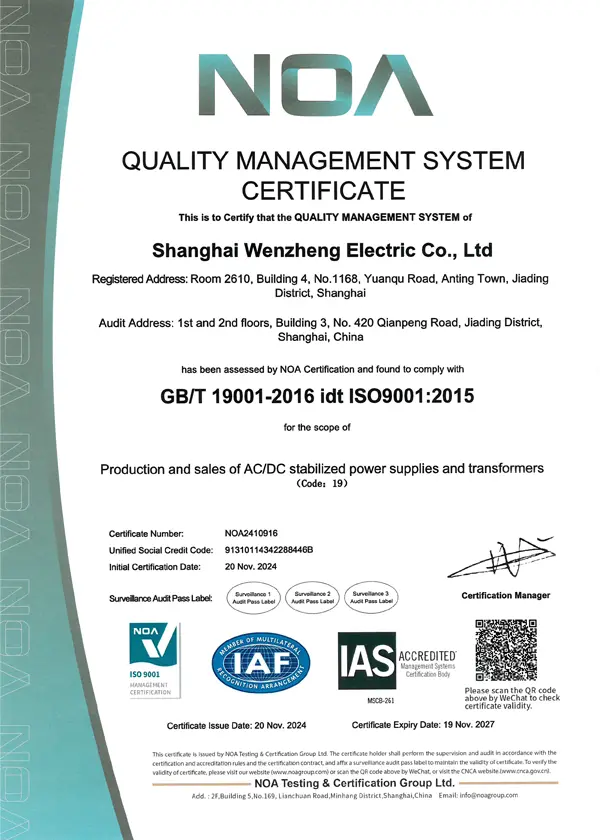
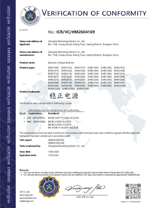
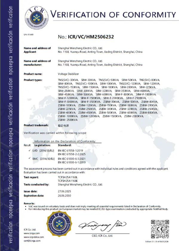
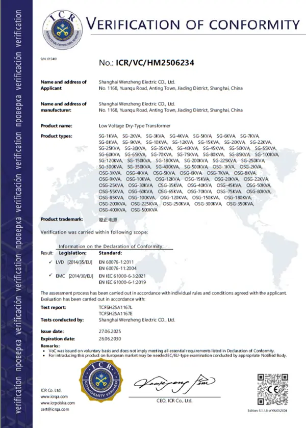
Certified quality management and product compliance for industrial power equipment.
Manufacturing processes, production equipment and quality control facilities at Winzele.
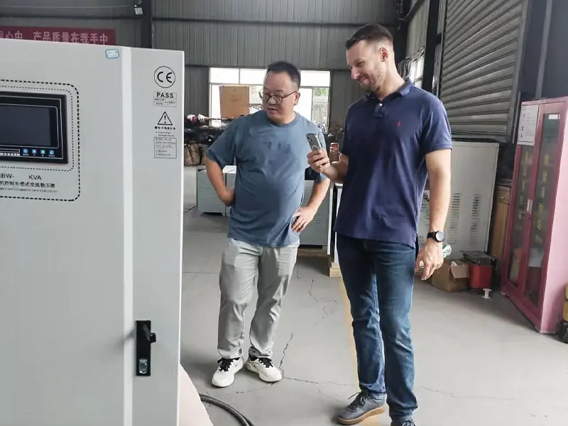
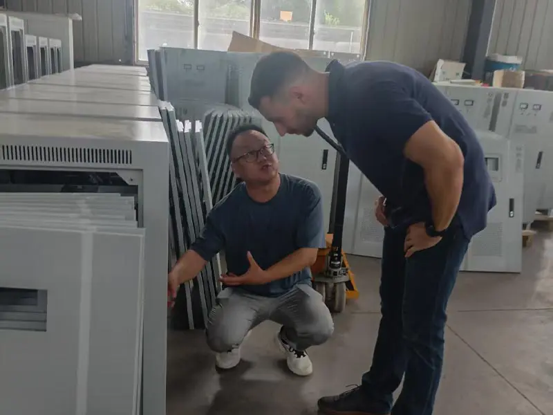
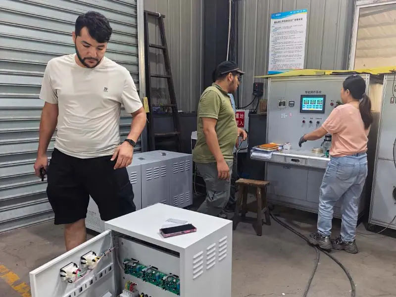
International customers visit Winzele manufacturing facilities for equipment inspection, technical discussion and project communication.

Contact our sales team for pricing, technical specifications, and delivery information.