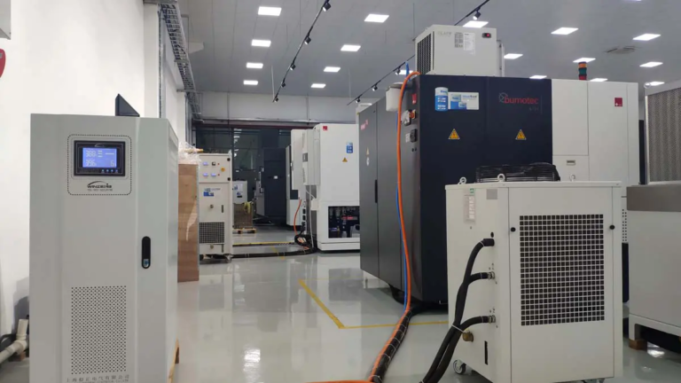
BUMOTEC S181 Mill-Turn Center


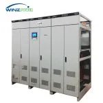
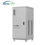
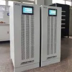
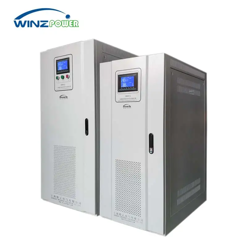
Industrial Automatic Voltage Regulator (AVR) for unstable three-phase power systems.
Rated Power:20~3000KVA
Grid Voltage(L-L):200V/208V/220V/380V/400V/415V/440V/480V
Phases: 3-phase
Input Range:±15%; ±20% / ±30% / ±40% Customizable
Input Frequency: 50/60Hz±10%
Output Accuracy:±1–5% (2% Standard)
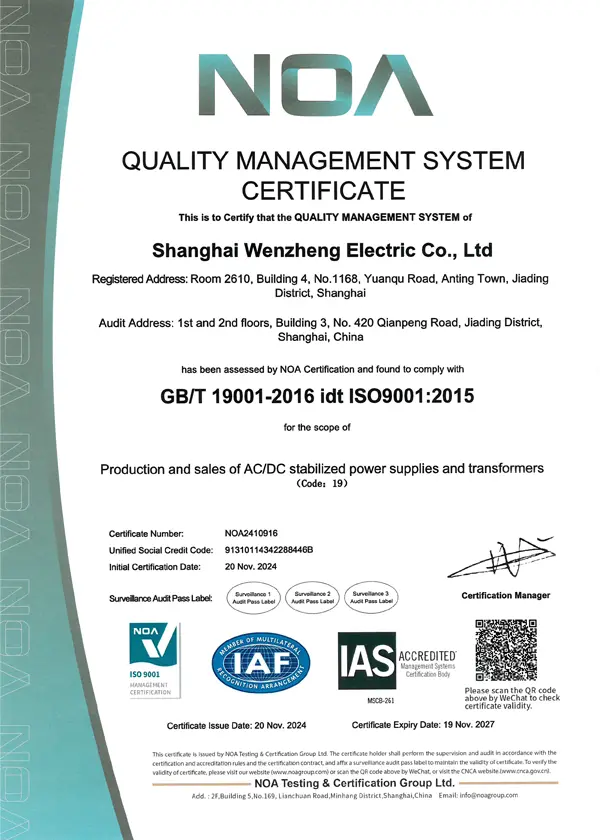
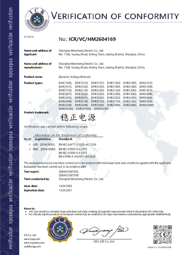
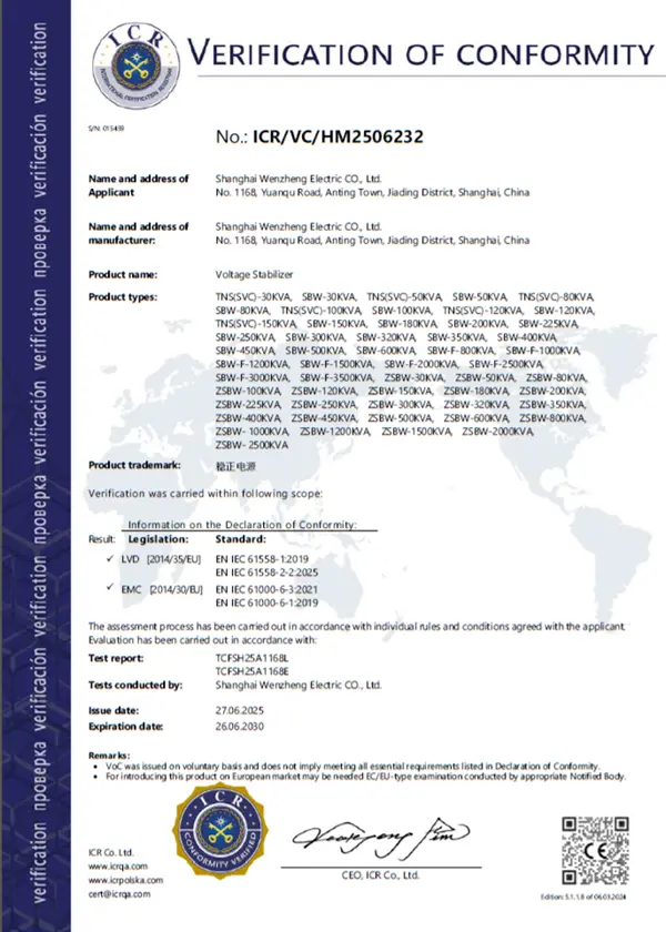
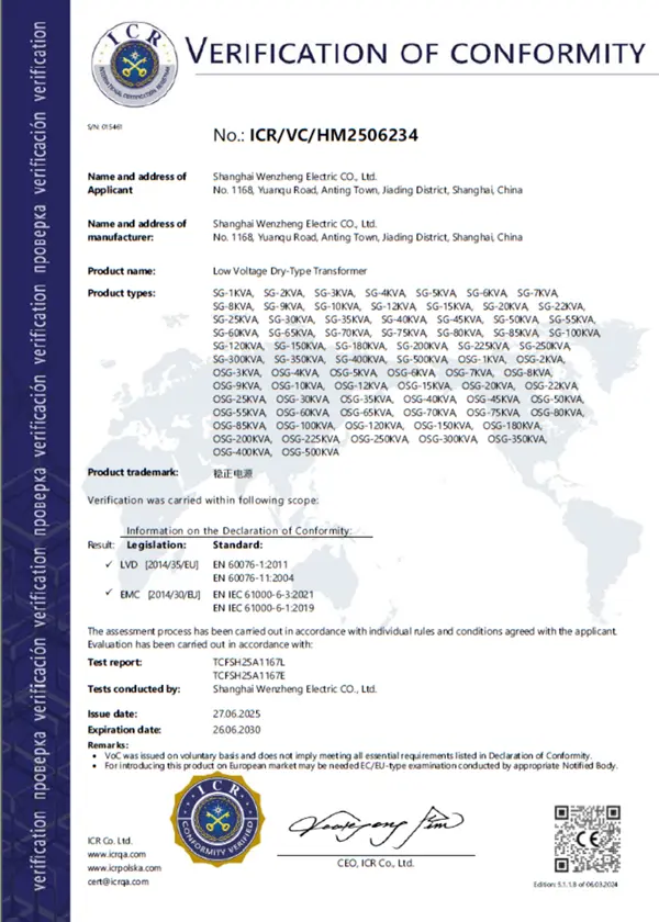
CE Certified | ISO 9001 | 20+ Years Power Manufacturing
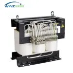
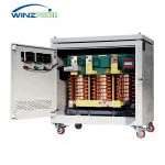
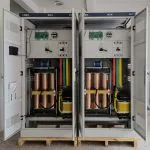
The SBW series is Winzele’s three-phase copper-column servo voltage stabilizer, designed and manufactured for industrial power systems requiring reliable voltage regulation. The servo motor compensation system uses closed-loop voltage control to continuously adjust output voltage and maintain stable power under unstable grid conditions.
Available from 20KVA to 3000KVA, the SBW series supports 50Hz/60Hz three-phase systems from 200V to 480V, with configurable input ranges, voltage levels, and transformer arrangements to match different industrial installation requirements. The series can be configured as an industrial automatic voltage regulator (AVR) for factories, production equipment, and centralized power distribution systems.
SBW is Winzele’s three-phase copper-column servo voltage stabilizer series, while the DBW series covers single-phase applications.
Quickly check whether your voltage problem matches the typical operating conditions of the SBW series.
A site may operate continuously below or above the nominal voltage due to weak distribution networks, long feeder runs, or heavy upstream loading. Equipment then operates outside its designed voltage range, which can reduce motor performance, increase electrical stress, and affect process stability. A voltage stabilizer regulates the output voltage toward the equipment’s required operating level.
Some grids experience continuous voltage variation during the day as loading conditions change. Equipment connected to such supplies may experience inconsistent performance and increased stress on electrical components and control systems. A voltage stabilizer helps maintain a more stable supply condition.
Large connected loads can cause noticeable voltage variation on a shared feeder, especially when high-current equipment starts or multiple loads operate simultaneously. The voltage at each machine depends on the condition of the connected network, so the stabilizer is typically installed at the incoming supply of the affected equipment or distribution point.
Representative applications include machine tools, automation equipment, printing equipment, pumps, compressors, HVAC systems, medical imaging systems, production lines, and factory distribution systems. These applications are representative rather than limiting; the same stabilizer family serves both individual equipment and centralized distribution points.
Note: SBW is intended for sustained or repeated voltage variation. Voltage sag, harmonics, transients, and frequency instability require other power-quality solutions.
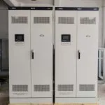
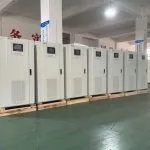
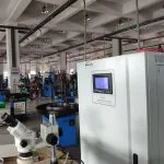
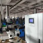
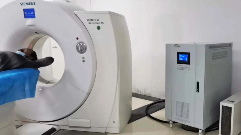
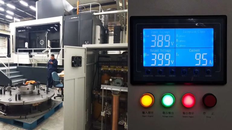
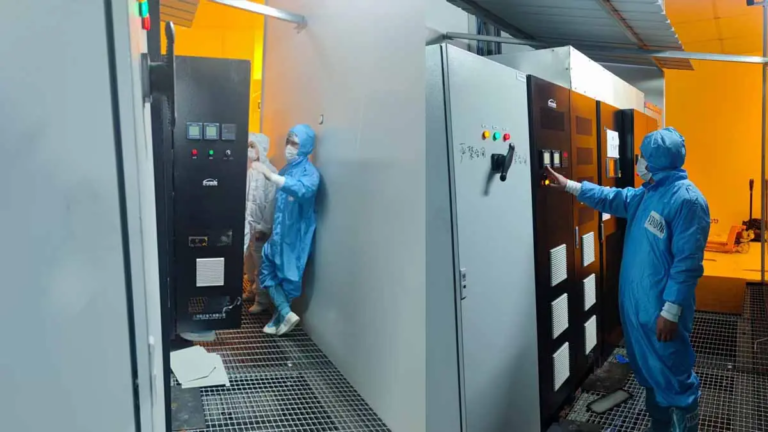
Selected installations using Winzele voltage stabilization equipment.
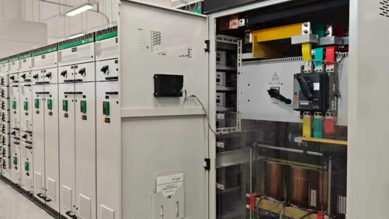
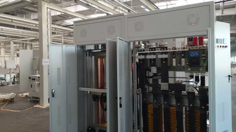
Looking for a similar project?
Explore more real installations by equipment, industry and capacity.
| Specification | Value |
|---|---|
| Three-phase SBW Capacity | 20KVA–3000KVA |
| Rated Voltage | Three-phase 200V/208V/220V/380V/400V/415V/440V/480V (any voltage customizable) |
| Input Voltage Range | (Rated Voltage)±20%, e.g. 380V±20%; ±15% / ±30% / ±40% configurable |
| Frequency | Input default 40~79Hz (customizable); output same as input |
| Output Voltage | Three-phase 380V/400V/415V (±10% adjustable); other voltages customizable |
| Output Voltage Accuracy | ±1-5% (2-5% for standard products) |
| Stabilization Time | <1 second (input voltage changes 10% within rated range, load 0-100%) |
| Efficiency | 98% |
| Output THD Increase | <0.1% (static and dynamic) |
Voltage Configuration Note: where the available grid voltage differs substantially from the required equipment voltage, voltage stabilization can be integrated with an appropriate transformer or voltage-conversion configuration. For wide voltage fluctuations, the input regulation range should be selected from the measured minimum and maximum site voltage during project sizing.
| Specification | Value |
|---|---|
| Applicable Load Type | Any load type (resistive, inductive, capacitive) |
| Overload Capacity | 120% 10min; 150% 1min |
| Bypass | Manual bypass; automatic bypass on internal fault optional |
| Protection Functions | Input overvoltage (OV), overcurrent (OC), undervoltage (UV); transformer overheat; short circuit |
| Isolation Transformer | Δ/Y or Y/Y (optional) |
| Communication | RS485 / RS232, MODBUS-RTU (TCP/IP, GPRS optional) |
| Specification | Value |
|---|---|
| Working Temperature & Relative Humidity | -35°C~+55°C; 10%-90% (20°C±5°C) |
| Altitude | <2000m; derate 10% per additional 1000m |
| IP Class | IP20 (outdoor IP33 etc. customizable) |
| Noise Level | <55dB |
Select based on the equipment rated power, rated current, and actual operating load. Check starting current and peak current where applicable. The load type determines the required reserve margin.
Calculate based on the loads operating simultaneously rather than simply adding every equipment nameplate rating. Consider the largest starting load, machine operating sequence, and the load mix connected to the same supply point.
Consider the factory transformer capacity, actual simultaneous demand, and future expansion requirements rather than the simple sum of all connected loads. Confirm whether isolation transformation or voltage conversion is required for the installation.
There is no universal 20% or 30% sizing rule; the required reserve margin depends on load characteristics and site conditions.
Winzele provides customized voltage stabilizer solutions for different grid conditions, equipment requirements, and installation environments.
The SBW series can be configured with:
Each system is manufactured according to project requirements, with electrical parameters, mechanical structure, and protection functions confirmed before production.
(Input voltage available for three-phase 200V/208V/220V/380V/400V/415V/440V/480V, etc.)
| Type | Capacity (kVA) | Current (A) | Dimension W×D×H (mm) |
|---|---|---|---|
| SBW-S-20KVA | 20 | 30 | 500*800*1000mm |
| SBW-S-30KVA | 30 | 45.6 | 500*800*1000mm |
| SBW-S-50KVA | 50 | 76 | 500*800*1000mm |
| SBW-S-80KVA | 80 | 121.6 | 550*880*1000mm |
| SBW-S-100KVA | 100 | 152 | 550*880*1000mm |
| SBW-S-120KVA | 120 | 182 | 620*920*1200mm |
| SBW-S-150KVA | 150 | 228 | 620*920*1200mm |
| SBW-S-180KVA | 180 | 274 | 700*1000*1300mm |
| SBW-S-200KVA | 200 | 304 | 700*1000*1300mm |
| SBW-S-250KVA | 250 | 380 | 1000*700*1500mm |
| SBW-S-300KVA | 300 | 456 | 1100*800*1900mm |
| SBW-S-350KVA | 350 | 532 | 1100*800*1900mm |
| SBW-S-400KVA | 400 | 608 | 1100*800*1900mm |
| SBW-S-500KVA | 500 | 760 | 1100*900*2000mm |
| SBW-S-600KVA | 600 | 912 | 1100*900*2000mm |
| SBW-S-800KVA | 800 | 1216 | 2000*1000*2000mm |
| SBW-S-1000KVA | 1000 | 1520 | 2000*1000*2000mm |
| SBW-S-1200KVA | 1200 | 1824 | 2000*1000*2000mm |
| SBW-S-1500KVA | 1500 | 2280 | 1350*1250*2200mm 3 cabinets |
| SBW-S-2000KVA | 2000 | 3040 | 1500*1350*2200mm 3 cabinets |
| SBW-S-2500KVA | 2500 | 3800 | 1500*1350*2200mm 3 cabinets |
| SBW-S-3000KVA | 3000 | 4560 | 1600*1350*2200mm 3 cabinets |
Explore SBW series options by capacity, voltage system, frequency and customized transformer configurations.
Four core processes ensure exceptional quality
High-grade silicon steel core for low loss and low-noise operation.
Automatic copper winding for precise layers and stable performance.
Complete voltage stabilizer assembly and electrical integration.
Electrical testing, functional checks, and final inspection before delivery.
Certified quality management and product compliance for industrial power equipment.
International customers visit Winzele manufacturing facilities for equipment inspection, technical discussion and project communication.
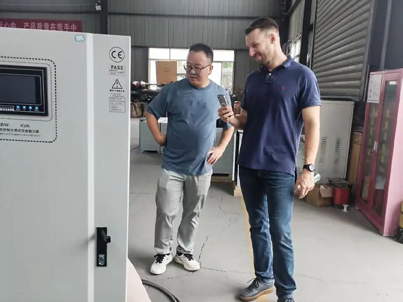
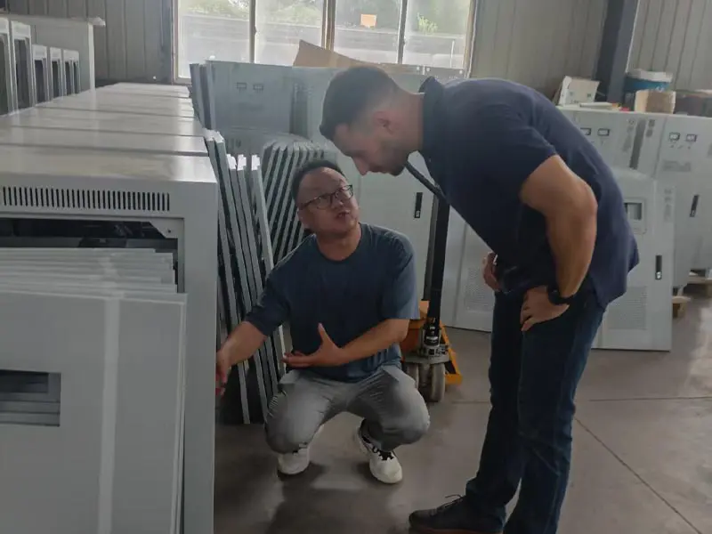

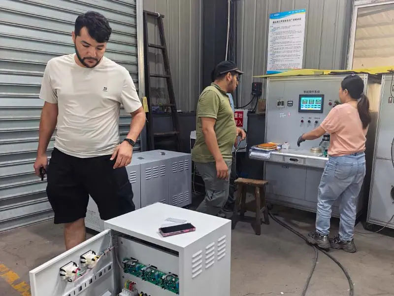
Manufacturing processes, production equipment and quality control facilities at Winzele.
The controller continuously measures the output voltage and compares it with the configured set value. When a sustained deviation is detected, it drives the servo motor. The servo motor moves the brush assembly along the regulating transformer, changing the regulating transformer output. The resulting compensation voltage is applied through the series compensating transformer, correcting the output voltage toward the configured value. The control system repeats this measurement and adjustment continuously while monitoring abnormal conditions through the configured protection functions.
Figure 1 shows the compensation path: the compensating transformer is connected in series with the main circuit and is fed by the regulating transformer. With the impedance voltage drop of the compensating transformer neglected, the output voltage is:
Uao = Uai + UBa
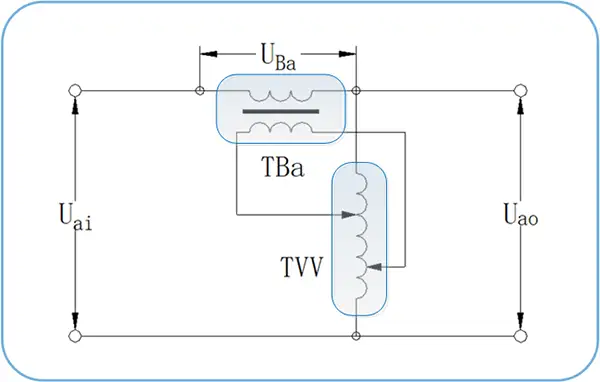
SBW servo motor voltage stabilizer compensation principle
For engineers requiring detailed calculation methods, including compensation voltage derivation, regulating transformer parameters, servo drive mechanism, speed reducer, chain wheel, and brush assembly details, please refer to the full technical datasheet.
Download Full SBW Technical Datasheet (PDF)
The datasheet includes detailed specifications for controller functions, communication interfaces, protection features, measurement parameters, and control settings.
Contact our sales team for pricing, technical specifications, and delivery information.