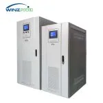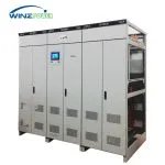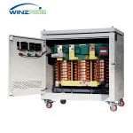


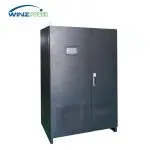
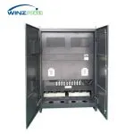

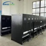
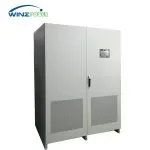
Dynamic Voltage Restorer
Fast voltage sag protection for sensitive industrial loads across 208 V, 400 V and 690 V systems.
Rated Capacity:30 kVA–3 MVA
System Voltage:208 / 400 / 690 V
Frequency:50 / 60 Hz
Response Time:≤ 2 ms
Minimum Residual Voltage:0%
Support Duration:0.4–30 s / Custom
Millisecond-response voltage protection for semiconductor, precision manufacturing and other sensitive industrial loads.
Product Introduction
Voltage sag is a sudden reduction in RMS voltage followed by a recovery to the normal level. It can be caused by short-circuit faults, lightning, large motor starting, line switching, or disturbances in the distribution system. Even a brief voltage sag can trip sensitive controllers, interrupt automated production lines, or shut down precision equipment.
The Dynamic Voltage Restorer (DVR) continuously monitors the utility supply and rapidly supports the protected load when an abnormal voltage condition is detected. Using high-speed IGBT power conversion and energy storage, the DVR maintains the load-side voltage during deep voltage sags and short interruptions, helping sensitive industrial equipment continue operating without disruption.
Manufactured by Shanghai Wenzheng Electric Co., Ltd., the Winzpower DVR series is designed and configured for industrial voltage-sag protection according to system voltage, protected-load capacity, sag depth and required support duration.
How DVR Protects the Load During a Voltage Sag?
When a voltage sag is detected, the DVR rapidly isolates the disturbed grid path and transfers load support to the inverter. Energy from the supercapacitor-backed DC link is converted through the IGBT inverter to maintain the load-side voltage until the utility supply returns to normal.
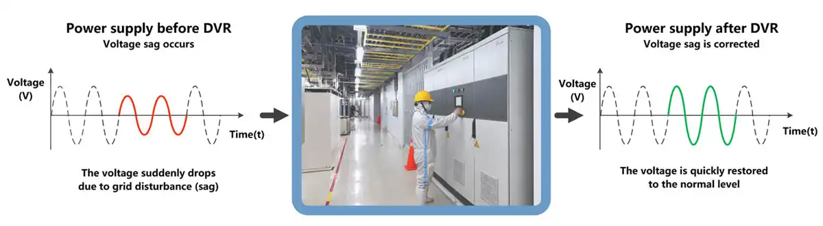
The protected load continues to receive a stable voltage even when the utility voltage drops sharply.
2ms Dynamic Voltage Recovery
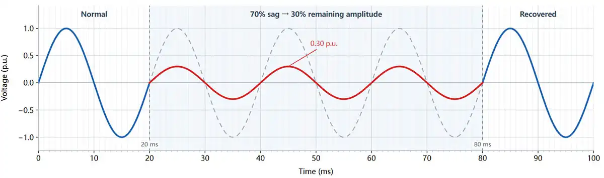
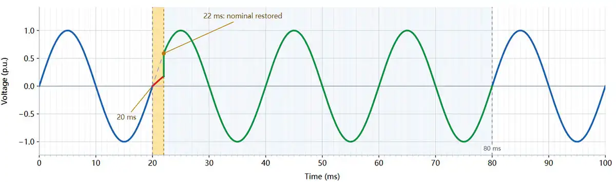
At 50 Hz, one electrical cycle is 20 ms. When a voltage sag is detected, the DVR responds within 2 ms to restore the protected-load voltage while maintaining the correct waveform phase.
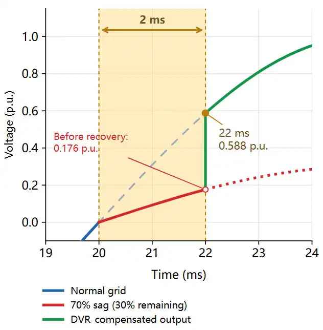 |
What Happens During the 2 ms Response?The voltage sag begins at the 20 ms zero crossing. During the response interval, the load briefly follows the sagged waveform at 30% of nominal amplitude. At 22 ms, the DVR completes the transfer to inverter support and restores the output to the nominal 50 Hz waveform at the correct instantaneous phase. At this point, the nominal waveform is approximately 0.588 p.u., compared with only 0.176 p.u. before recovery. 2 ms represents only 10% of one 50 Hz electrical cycle. |
Illustrative 50 Hz waveform. Actual transient behavior depends on the system, load and project configuration.
Real DVR Installations
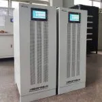
Field-installed DVR systems protecting sensitive semiconductor and precision manufacturing loads from voltage sags and short-duration power disturbances.
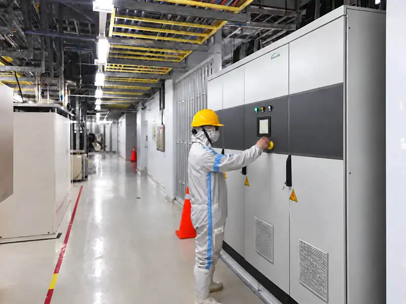
Semiconductor Manufacturing Facility — DVR CommissioningOn-site DVR commissioning for sensitive semiconductor production equipment, providing fast voltage sag protection and maintaining stable power to critical loads. |
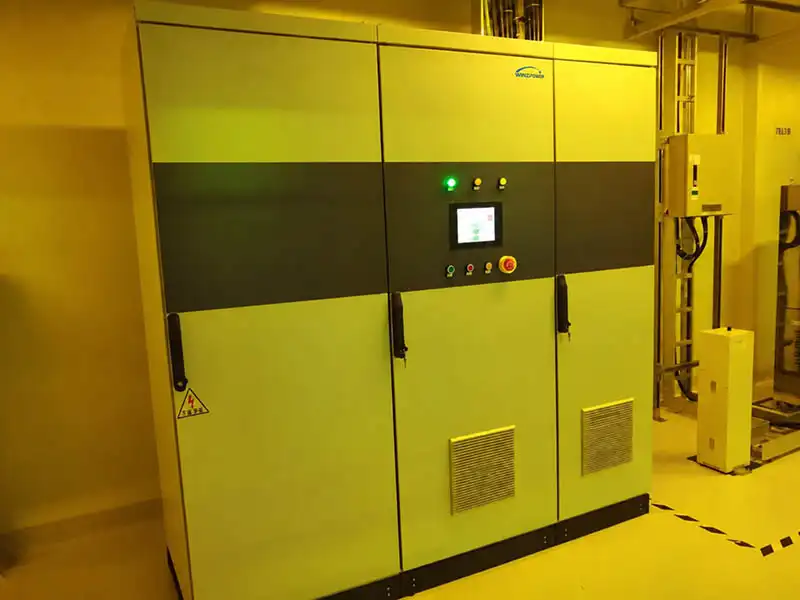
Semiconductor Cleanroom — DVR InstallationDVR installed in a semiconductor cleanroom environment to protect precision process equipment from deep voltage sags and short interruptions. |
Project details are limited to protect customer confidentiality and sensitive production information.
Related DVR Case Studies & Selection Guide
- 2 × 1500 kVA DVR for wafer-level advanced packaging
- 500 kVA DVR for wafer and semiconductor testing
- 300 kVA DVR for semiconductor packaging and testing
- DVR Selection & RFQ Guide — how to specify a DVR: the project information required for selection and quotation
DVR Operating Modes
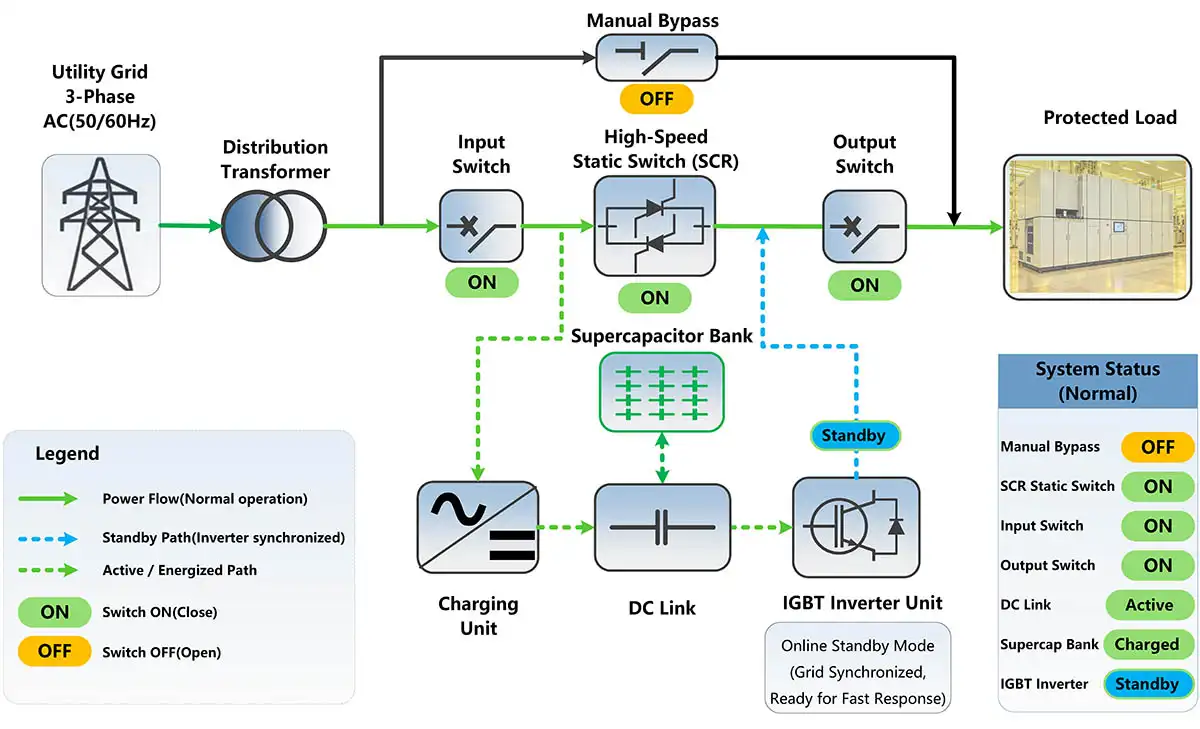
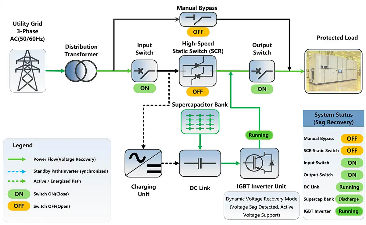
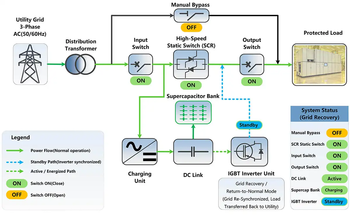
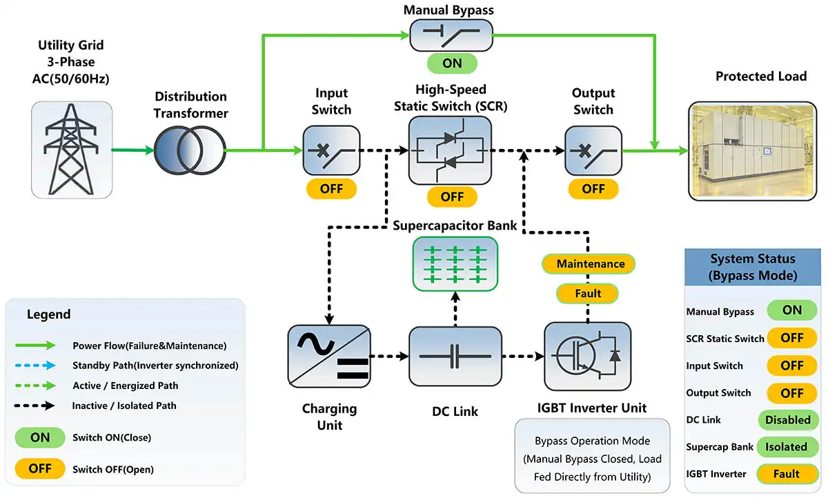
The DVR uses different power paths for normal operation, voltage sag recovery, grid restoration and maintenance bypass. The diagrams below show how the static switch, DC link, supercapacitor and inverter work together in each operating state.
1.Online Standby Mode
Under normal grid conditions, utility power supplies the protected load through the static power path. The DC link remains energized and the supercapacitor bank stays charged, while the inverter remains synchronized and ready without carrying the main load power.
2.Dynamic Voltage Recovery Mode
Once a voltage sag reaches the protection threshold, the inverter immediately becomes the active source for the protected load. Energy stored in the supercapacitor bank is delivered through the DC link and IGBT inverter, maintaining the load-side voltage while the disturbed utility condition continues.
3.Grid Recovery / Return-to-Normal Mode
When the utility voltage returns to an acceptable range, load supply is transferred back to the normal grid path. The inverter returns to standby and the charging circuit replenishes the DC link and supercapacitor bank, restoring the system to its ready state for the next disturbance.
4.Manual Maintenance Bypass Mode
During scheduled maintenance, the manual bypass path can supply the protected load directly from the utility while the DVR power-conversion section is isolated for inspection or servicing. This maintenance bypass state is separate from the DVR’s automatic fail-safe bypass function.
Technical Parameters
The DVR is designed for fast protection of sensitive industrial loads against deep voltage sags and short-duration power disturbances. System capacity, protection duration and cabinet configuration can be selected according to the protected load and site conditions.
| System & Voltage Sag Protection | |
|---|---|
| Rated Voltage | 208 V / 400 V / 690 V |
| Rated Capacity | 30 kVA – 3 MVA, depending on system voltage |
| Input Frequency | 50 / 60 Hz ±10% |
| Minimum Residual Voltage | 0% |
| Voltage Sag Protection | Single-phase, two-phase and three-phase voltage sag |
| Support Duration | ≥400 ms standard; 0.4–30 s project configurable; other durations subject to project confirmation |
| Continuous Sag Protection | Supported, subject to event profile and energy-storage sizing |
| Inverter & Load Output | |
| Response Time | ≤ 2 ms |
| Voltage Setting Time | 1 – 5 ms |
| Output Frequency | 50 / 60 Hz ±1% |
| Output Voltage Distortion | THDu < 2.5% under linear load conditions |
| Voltage Unbalance | < 3% with 100% unbalanced load |
| Inverter Overload | 150% for 30 s |
| Protection Current | 200% |
| Permissible Motor Load | Up to 50% of rated DVR capacity |
| Grid & System Performance | |
| System Efficiency | Up to 99.2% |
| Grid-Side Overload Capability | 150% for 60 s / 500% for 1 s / 2000% for 200 ms |
| Overvoltage Category | Category III |
| Energy Storage | |
| Energy Storage | Supercapacitor |
| Recharge Time | < 45 s |
| Charge Cycle Life | > 500,000 cycles |
| Design Life | > 20 years at 25°C |
| Fail-Safe Bypass | |
| Bypass Overload Capability | 500% for 30 s |
| Contactor Closing Time | 20 ms |
| Breaker Closing Time | 80 ms, optional |
| Monitoring & Communication | |
| Line-Voltage Inspection Cycle | 50 μs |
| Event Log Resolution | 1 ms |
| Measurement Method | Half-cycle RMS according to IEC 61000-4-30 |
| HMI | 10-inch graphic TFT color display |
| Communication | Modbus/TCP (Ethernet), RS485; GPRS / remote communication optional by configuration |
| Operating Environment | |
| Operating Temperature | −25°C to +45°C; 2% capacity derating per °C above 40°C |
| Relative Humidity | < 95%, non-condensing |
| Installation Altitude | 0–3000 m; 1% capacity derating per 100 m above 2000 m |
| Protection Class | IP21 / IP23, other protection classes optional |
| IEC Pollution Degree | 2 |
| Noise | < 60 dB |
Technical specifications may vary with system voltage, protected-load capacity, required sag depth and support duration. Final ratings and system configuration are confirmed according to project requirements.
Manufacturer & Certification
| Manufacturer & CE Certification Details | |
|---|---|
| Manufacturer | Shanghai Wenzheng Electric Co., Ltd. |
| Product | Dynamic Voltage Restorer (DVR) |
| Certification | CE Certified — LVD & EMC |
| EU Directives | LVD 2014/35/EU EMC 2014/30/EU |
| Certificate / Verification No. | ICR/VC/HM2604169 |
| Applicable Standards | EN IEC 62477-1:2023+AC:2024 EN IEC 61000-6-2:2019 EN IEC 61000-6-4:2019 EN 61000-4-34:2007+A2:2025 |
| Issue Date | 14 Apr 2026 |
| Expiry Date | 13 Apr 2031 |
CE certification applies to the DVR product types listed in the certification document. Commercial model numbers used on this page provide additional voltage, capacity and wiring information for project selection.
Certifications & Quality Management
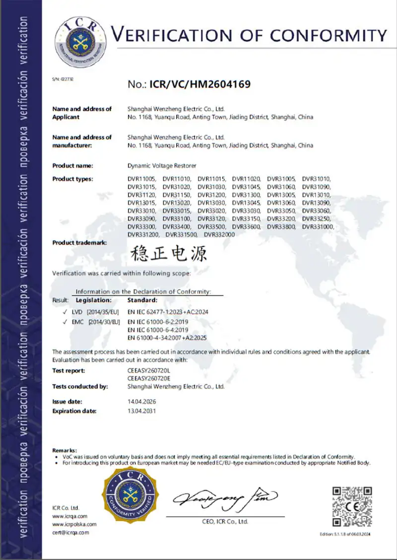
CE Certification — LVD & EMC
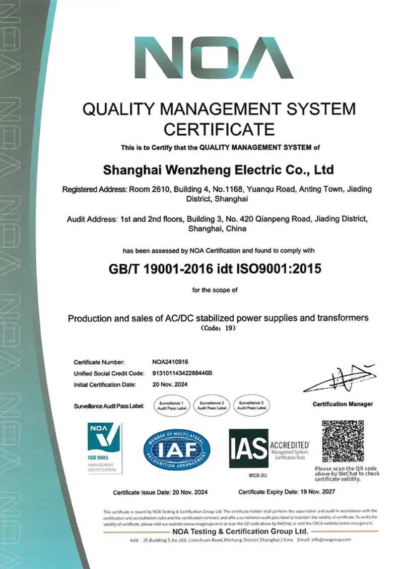
ISO 9001 Quality Management System
Models & Selection Guide
DVR model selection is based on system voltage and protected-load capacity. Voltage sag depth and support duration are configured according to the application requirements and site conditions.
Model format: DVR-[Rated Capacity]-[Voltage Class]-3P4L
Commercial model numbers are structured for project selection by capacity, system voltage and wiring. CE Product Types use a separate certification code based on input/output phase configuration and rated capacity.
Commercial Model: DVR-500-0.4-3P4L
CE Product Type: DVR33500
Meaning: 3-phase input / 3-phase output / 500 kVA
In the CE Product Type code, 33 means 3-phase input / 3-phase output, and the following digits identify rated capacity in kVA. The CE Product Type does not encode the commercial model’s voltage class; 0.208, 0.4 and 0.69 continue to identify the system voltage in the commercial model.
1.208 V DVR Series
Three-phase, four-line configuration for 208 V power systems.
| Commercial Model | Capacity | Rated Current | CE Product Type |
|---|---|---|---|
| DVR-30-0.208-3P4L | 30 kVA | 83 A | DVR33030 |
| DVR-50-0.208-3P4L | 50 kVA | 139 A | DVR33050 |
| DVR-75-0.208-3P4L | 75 kVA | 208 A | — |
| DVR-100-0.208-3P4L | 100 kVA | 278 A | DVR33100 |
| DVR-150-0.208-3P4L | 150 kVA | 416 A | DVR33150 |
| DVR-300-0.208-3P4L | 300 kVA | 833 A | DVR33300 |
| DVR-500-0.208-3P4L | 500 kVA | 1388 A | DVR33500 |
| DVR-750-0.208-3P4L | 750 kVA | 2082 A | — |
| DVR-1000-0.208-3P4L | 1000 kVA | 2776 A | DVR331000 |
CE Product Type is shown where the rated capacity corresponds to a DVR33-series product type listed in the current CE certification document. “—” indicates that this commercial capacity is not separately listed under the current certificate product-type list; it does not change the availability of the commercial model.
2.400 V DVR Series
Three-phase, four-line configuration for 400 V industrial power systems.
| Commercial Model | Capacity | Rated Current | CE Product Type |
|---|---|---|---|
| DVR-30-0.4-3P4L | 30 kVA | 43 A | DVR33030 |
| DVR-50-0.4-3P4L | 50 kVA | 72 A | DVR33050 |
| DVR-75-0.4-3P4L | 75 kVA | 108 A | — |
| DVR-100-0.4-3P4L | 100 kVA | 144 A | DVR33100 |
| DVR-200-0.4-3P4L | 200 kVA | 288 A | DVR33200 |
| DVR-300-0.4-3P4L | 300 kVA | 432 A | DVR33300 |
| DVR-500-0.4-3P4L | 500 kVA | 720 A | DVR33500 |
| DVR-750-0.4-3P4L | 750 kVA | 1080 A | — |
| DVR-1000-0.4-3P4L | 1000 kVA | 1440 A | DVR331000 |
| DVR-1250-0.4-3P4L | 1250 kVA | 1800 A | — |
| DVR-1500-0.4-3P4L | 1500 kVA | 2160 A | DVR331500 |
| DVR-2000-0.4-3P4L | 2000 kVA | 2800 A | DVR332000 |
CE Product Type is shown where the rated capacity corresponds to a DVR33-series product type listed in the current CE certification document. “—” indicates that this commercial capacity is not separately listed under the current certificate product-type list; it does not change the availability of the commercial model.
3.690 V DVR Series
Three-phase, four-line configuration for high-capacity 690 V industrial systems.
| Commercial Model | Capacity | Rated Current | CE Product Type |
|---|---|---|---|
| DVR-300-0.69-3P4L | 300 kVA | ≈251 A | DVR33300 |
| DVR-500-0.69-3P4L | 500 kVA | ≈418 A | DVR33500 |
| DVR-750-0.69-3P4L | 750 kVA | ≈628 A | — |
| DVR-1000-0.69-3P4L | 1000 kVA | ≈837 A | DVR331000 |
| DVR-1250-0.69-3P4L | 1250 kVA | ≈1046 A | — |
| DVR-1500-0.69-3P4L | 1500 kVA | ≈1255 A | DVR331500 |
| DVR-2000-0.69-3P4L | 2000 kVA | ≈1674 A | DVR332000 |
| DVR-3000-0.69-3P4L | 3000 kVA | ≈2510 A | — |
CE Product Type is shown where the rated capacity corresponds to a DVR33-series product type listed in the current CE certification document. “—” indicates that this commercial capacity is not separately listed under the current certificate product-type list; it does not change the availability of the commercial model.
Rated current values are based on the nominal three-phase system voltage. Final DVR configuration, cabinet arrangement and energy-storage capacity depend on the required residual voltage protection level and support duration.
Protection Configuration
The DVR base model defines capacity, voltage class and wiring only. Support duration and compensation depth are project-specific configuration items and are not included in the model code.
| Selection Item | Configuration |
|---|---|
| Support Duration | Standard configuration: ≥400 ms |
| Extended / Project-Configured Duration | 0.4–30 s; other or special durations subject to project confirmation |
| Minimum Residual Voltage | Project-defined, down to 0% |
| Required Sag Depth | Project-defined according to site conditions |
| Sag Type | Single-phase / two-phase / three-phase |
| Continuous Sag Events | Supported, subject to event profile and energy-storage sizing |
Residual voltage is the voltage remaining during a sag: 70% voltage sag corresponds to 30% residual voltage, and 100% voltage sag corresponds to 0% residual voltage.
DVR selection should be based on: System Voltage → Protected Load Capacity → Minimum Residual Voltage → Required Support Duration
Example — 400 V / 500 kVA / 30% residual voltage / 1 s support duration
Base model: DVR-500-0.4-3P4L
Project configuration: 70% voltage sag protection / 30% residual voltage / 1 s support duration
Support duration and compensation depth are project configuration items and are not part of the model code. Longer or special support durations are confirmed per project.
DVR Architecture Comparison
Different voltage-sag protection systems use different methods to maintain load voltage. The comparison below highlights the main architectural differences between stored-energy DVR systems and series-injection voltage compensation systems.
1.Winzpower DVR — Stored-Energy Inverter Support
| Architecture | High-speed static switching, DC link, supercapacitor bank and IGBT inverter |
| Energy Source During Sag | Stored energy from the supercapacitor bank |
| Protection Method | The disturbed grid path is isolated and the inverter actively supports the protected load |
| Residual Voltage Capability | Configurable down to 0% residual voltage |
| Response Time | ≤ 2 ms |
| Support Duration | Configurable according to project requirements |
2.ABB PCS100 AVC-40 — Series Voltage Injection
| Architecture | Voltage-source inverter with series-connected injection transformer |
| Energy Storage | No battery or dedicated energy-storage system required |
| Energy Source During Sag | Correction energy is drawn from the connected utility supply |
| Protection Method | A correction voltage is injected in series with the utility voltage |
| Sag Correction Response | Initial response < 250 μs; complete correction < half a cycle |
| Published Sag Correction Capability | Up to 40% correction, model dependent |
3.Schneider PowerLogic DVR — Series Compensation
| Architecture | Rectifier, inverter, static bypass and booster transformer |
| Energy Storage | No batteries or dedicated energy-storage components required |
| Energy Source During Sag | Compensation energy is taken directly from the power line |
| Protection Method | The inverter generates a compensating voltage through the booster transformer |
| Response Time | < 3 ms |
| Published Sag Capability | Model-dependent three-phase sag correction; up to 60% sag models are available |
Key architectural difference: Winzpower DVR uses stored energy to support the protected load during deep voltage disturbances, while series-injection systems mainly generate a corrective voltage using energy taken from the remaining utility supply.
Product capabilities shown for ABB and Schneider are based on their published technical documentation. Available configurations and ratings may vary by model and project.
Where DVR Is Used
DVR systems are intended for industrial loads that cannot tolerate even short-duration voltage sags or interruptions. They are particularly useful where a brief disturbance can trip control systems, stop production, damage work-in-process, or require a lengthy restart.
What Causes Voltage Sags?
Voltage sags can originate from utility-side disturbances as well as from events inside an industrial facility. Common causes include short-circuit faults, lightning, large motor starting, network switching, and accidental damage to the power distribution system.
Because many voltage sag events originate outside the protected facility, they cannot always be prevented at the source. For sensitive industrial loads, the practical objective is therefore to prevent the disturbance from interrupting the process.
Why Voltage Sags Matter in Industrial Facilities
A voltage sag may last only a fraction of a second, but sensitive industrial equipment can react much faster than the utility supply recovers. The resulting trip, reset or process interruption can create downtime and production losses far beyond the duration of the electrical event itself.
For high-value or continuous production processes, the cost of a voltage sag is therefore determined not only by the sag duration, but by the resulting process interruption, material loss and restart time.
Dynamic Voltage Restorer FAQ
What does a 70% voltage sag mean?
Voltage sag depth is calculated from the voltage lost, while residual voltage is the voltage remaining. Sag depth = 1 − residual voltage (p.u.). A 70% voltage sag therefore leaves 30% residual voltage. On a 400 V system that is approximately 120 V residual line voltage; on a 208 V system it is approximately 62 V. Protection is specified by the minimum residual voltage the DVR can ride through, equivalently the maximum voltage-sag depth.
Can the DVR protect the load when residual voltage falls to 0%?
Yes. The DVR can be configured for protection down to 0% residual voltage, which represents the most severe short-duration condition — a complete collapse of the supply voltage. In that case the inverter supplies the protected load entirely from the supercapacitor bank, so the achievable protection time depends on the DVR rating and the configured support duration. This is a short-duration voltage sag function rather than continuous UPS-style backup; an application that must ride through a sustained outage has to be specified with the appropriate support duration.
What does the ≤2 ms DVR response time mean?
A 50 Hz cycle lasts 20 ms, so a 2 ms response time corresponds to about 10% of one cycle. Within 2 ms, the DVR detects the voltage sag, isolates the disturbed grid path, and restores the protected-load voltage through synchronized inverter support. Because this protection action finishes inside the cycle, the output voltage is restored at the correct instantaneous phase instead of at an arbitrary point in the waveform. This fast transition helps sensitive drives, controllers and contactors ride through short disturbances, subject to their voltage tolerance and the configured DVR rating.
How long can the DVR support the protected load?
The standard protection duration is ≥400 ms. Project-configured durations are available from 0.4 s to 30 s, while other or special durations are subject to project confirmation. Support duration is not encoded in the base model number: the model defines voltage class, capacity and wiring only. Longer support durations require more stored energy, which means a larger supercapacitor bank and a different cabinet configuration, which is why support duration and compensation depth are treated as project configuration items.
Why does this DVR use supercapacitors instead of batteries?
Voltage sag protection is a short-duration, high-power duty: the DVR must deliver a large current almost immediately, for hundreds of milliseconds rather than hours. Supercapacitors suit that profile, with fast power delivery, a charge cycle life of more than 500,000 cycles, a recharge time below 45 s and a design life of more than 20 years at 25°C. They reduce the dependence on battery-style energy storage, whose cycle life and replacement interval are matched to a different duty — long outage backup rather than repeated deep sag events.
Can the DVR protect against single-phase and unbalanced voltage sags?
Yes. The DVR supports single-phase, two-phase and three-phase voltage sags and can handle unbalanced voltage disturbances. The protection actually available at a site is defined during configuration, where sag depth, protected load capacity and system wiring are reviewed together. Unbalanced or weak-supply conditions are therefore worth describing when the rating is selected, instead of being assumed to be covered unconditionally by every configuration.
Is a DVR the same as a UPS?
No. Under normal conditions the utility supplies the protected load through the DVR’s static power path while the inverter remains synchronized and ready. When a voltage sag or short interruption occurs, the DVR intervenes and supports the load from stored energy. Its design target is short-duration power quality disturbance. A UPS typically provides continuously conditioned power and is configured with batteries sized for longer power interruptions. Which solution is appropriate depends on whether the requirement is voltage sag protection or long-duration outage backup.
How is this stored-energy DVR different from a series-injection AVC or DVR?
The difference is architectural. This DVR uses high-speed static switching, a DC link, a supercapacitor bank and an IGBT inverter: the disturbed grid path is isolated and the inverter actively supports the protected load from stored energy, with protection configurable down to 0% residual voltage. Series-injection AVC or DVR systems inject a corrective voltage in series with the utility voltage and generally use the remaining grid voltage as their primary energy source. The two approaches have different limits, so the suitable choice depends on sag depth, required support duration and the load being protected.
How do I select the correct DVR capacity and configuration?
Selection follows the sequence used in this page: system voltage → protected load capacity → minimum residual voltage → required support duration. Useful project information includes system voltage and frequency, protected load kVA, wiring and phase configuration, minimum expected residual voltage, required support duration, load type and any motor or non-linear load proportion. The DVR should be sized for the sensitive load that actually needs protection rather than for the total transformer capacity of the plant, since protecting the whole plant usually results in an oversized configuration.
Can the DVR handle repeated voltage sag events?
Yes. Repeated or continuous sag events can be supported, subject to the event profile and energy-storage sizing, and the supercapacitor bank recharges in less than 45 s. That capability is not unlimited in frequency: the achievable repetition interval depends on sag depth, sag duration, the time between events, the protected load and the selected energy storage configuration. Where repeated or high-frequency sags are part of normal site conditions, the actual disturbance profile should be provided during configuration so that the storage capacity and cabinet arrangement are matched to the real event pattern.
Get a Quick Quote
Contact our sales team for pricing, technical specifications, and delivery information.