

2 × 1500 kVA DVR Systems for Wafer-Level Advanced Packaging
JSI SEMICONDUCTOR INTEGRATION (SHAOXING) CO., LTD. installed two 1,500 kVA Winzpower Dynamic Voltage Restorer systems for a wafer-level advanced packaging process section. The 3-phase 400 V project pairs two 1,250 kVA process transformers with two 1,500 kVA DVR systems—one DVR on the low-voltage side of each transformer.
Each DVR is configured for a maximum voltage sag depth of 40%, equivalent to 60% residual voltage, with a required support duration of 1 second. Unlike a single-equipment feeder project, this application uses the Dynamic Voltage Restorer (DVR) to protect multiple downstream process-load feeders as one process-section protection boundary for each transformer-DVR chain.
Project Background
JSI Semiconductor operates in semiconductor manufacturing and wafer-level advanced packaging. The documented project area is supplied by two 1,250 kVA process transformers. Instead of installing voltage-sag protection only at one downstream machine feeder, the project places a DVR at each process transformer’s low-voltage side.
This arrangement extends the protected boundary to the downstream process section supplied by each transformer. Multiple load feeders are therefore included behind each DVR, while the two electrical paths remain distinct: each transformer corresponds to its own 1,500 kVA DVR system.
The customer does not disclose the identities, brands, recipes, or internal arrangement of the downstream production equipment. This case uses only the confirmed application category—wafer-level advanced packaging process loads—and the documented electrical configuration.
Voltage Sag Protection Requirement
The project requirement defines a 40% sag depth and 60% residual voltage. The values are complementary: residual voltage equals 100% minus sag depth.
| Item | Project Requirement |
|---|---|
| Customer | JSI SEMICONDUCTOR INTEGRATION (SHAOXING) CO., LTD. |
| Industry | Semiconductor / wafer-level advanced packaging |
| System Voltage | 400 V |
| Phase | 3-phase |
| Process Transformers | 2 × 1,250 kVA |
| DVR Configuration | 2 × 1,500 kVA DVR systems |
| Maximum Sag Depth | 40% |
| Minimum Residual Voltage | 60% |
| Required Support Duration | 1 s |
| Installation Point | Process transformer low-voltage side |
| Protected Load | Multiple downstream process-load feeders in the protected process section |
DVR Configuration
The installed solution consists of two 3-phase, 400 V DVR systems, each rated 1,500 kVA. One DVR is assigned to each 1,250 kVA process transformer. The resulting arrangement is two repeated protection chains:
1,250 kVA Process Transformer → 1,500 kVA DVR → Protected Downstream Process Section
The two-DVR configuration should not be interpreted as one DVR protecting both transformers. Each transformer low-voltage output has its own DVR and its own downstream protection boundary. Both systems share the same project requirement of 40% sag depth, 60% residual voltage, and 1-second support duration.
The supplied project record does not specify cabinet dimensions, equipment weight, transformer impedance, short-circuit level, switchgear models, or the ratings of individual downstream branch loads. No values are invented for those items.
Electrical Connection and Protection Boundary
The single-line diagram below represents one of the two transformer-DVR chains. The same topology is applied twice in the project. After the process transformer, the 1,500 kVA DVR is connected on the 400 V low-voltage side. The protected section begins downstream of the DVR and includes multiple process-load feeders supplied from that transformer path.
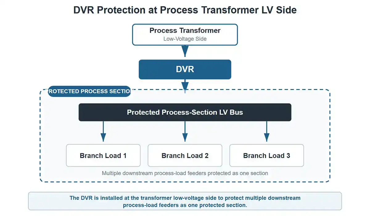
This topology makes whole process-section protection the defining feature of the project. It differs from protecting a single machine or one dedicated equipment feeder because multiple downstream feeders sit within each protected boundary.
On-Site Installation
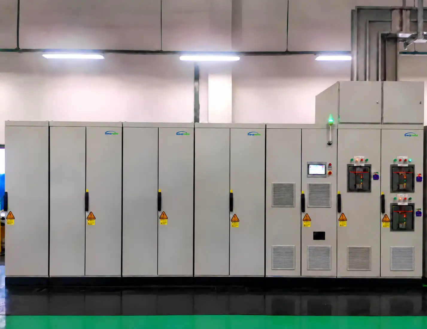
The first photograph documents one installed 1,500 kVA, 400 V DVR assembly. It shows the actual multi-cabinet installation without identifying the downstream semiconductor process equipment.
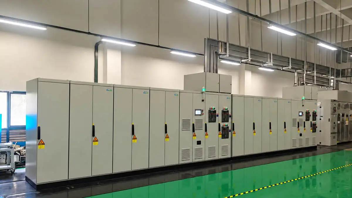
The wider installation photograph documents the two-system project arrangement in the industrial electrical installation area.
Engineering Outcome
The two DVR systems provide process-section-level voltage-sag protection downstream of the two process transformers. Each installed system is configured to support its protected section through the specified 40% sag depth and 1-second support-duration requirement.
The confirmed outcome is the completed two-system installation and its defined protection topology. The available evidence does not include a post-installation sag-event waveform, equipment trip history, production-loss statistics, or measured downtime reduction. This case therefore does not claim zero trips, a recorded ride-through success rate, or a quantified production benefit.
Project Summary
The JSI project is a 3-phase 400 V process-section protection application built around two 1,250 kVA process transformers and two corresponding 1,500 kVA DVR systems. Each DVR is installed at one transformer low-voltage side and protects multiple downstream process-load feeders. The configured requirement is 40% sag depth, 60% residual voltage, and 1 second of support.
For guidance on defining protected-load capacity, voltage-sag conditions, and support duration for a comparable project, see the DVR Selection & RFQ Guide.
Detailed process-equipment information is intentionally omitted to protect customer confidentiality and semiconductor production security.
Related Product
Dynamic Voltage Restorer (DVR): Winzpower DVR systems provide voltage-sag compensation on the low-voltage side of a protected feeder or process transformer, so the protected load is supported through the specified sag depth and support duration.


