

How to Specify a Dynamic Voltage Restorer (DVR): Information Required for Selection and Quotation
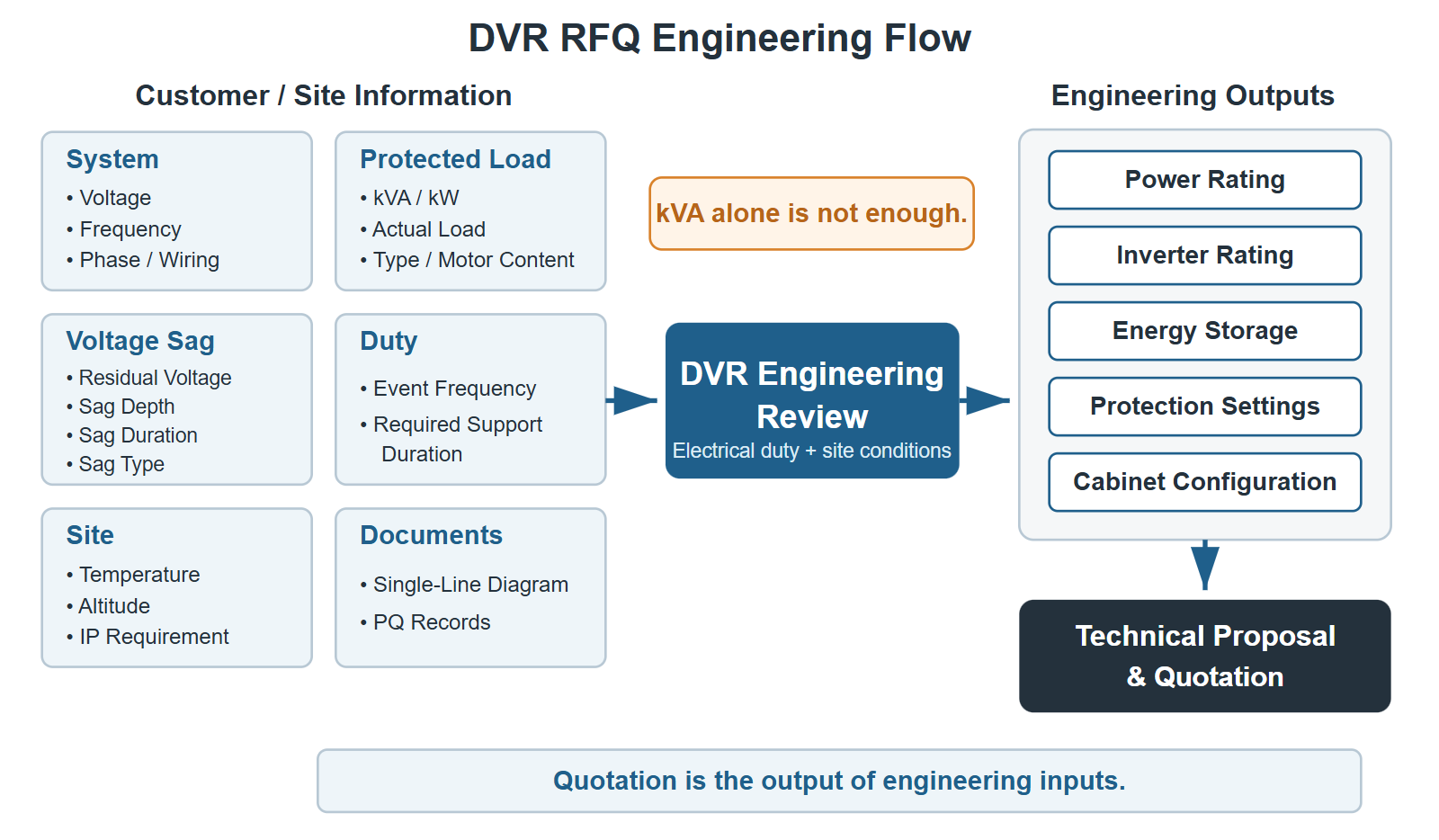
A request such as “Please quote a 500 kVA DVR” is not enough to determine the correct Dynamic Voltage Restorer configuration. Capacity is only one part of DVR selection and DVR sizing. The same 500 kVA protected load may require a different current rating, inverter arrangement, energy-storage capacity, cabinet configuration, or protection setting when the system voltage, load characteristics, voltage-sag event, or required support duration changes.
DVR capacity alone is not enough to determine the correct configuration or quotation. The correct DVR configuration depends on both the protected load and the characteristics of the voltage-sag event.
For a useful DVR quotation, the supplier normally needs to understand the system voltage and frequency, phase and wiring arrangement, protected load, actual operating load, load type, sag depth, residual voltage, sag duration, event pattern, required ride-through time, and site conditions. A single-line diagram and power quality record can often answer several of these questions more accurately than a short equipment list.
Why DVR Capacity Alone Is Not Enough
A kVA value describes apparent power, but it does not define the complete electrical duty of a DVR. For example, a 500 kVA load at 208 V has a substantially different rated current from a 500 kVA load at 690 V. Likewise, supporting a load through a shallow sag for a fraction of a second is a different energy duty from supporting the same load through a deep sag for several seconds.
Load behavior also matters. A stable resistive load, a group of motors, and semiconductor process equipment with VFD and servo loads can have different current waveforms, transient demands, overload conditions, and undervoltage tolerances. The DVR power stage, inverter capacity, stored energy, bypass and switching devices, protection settings, and enclosure arrangement therefore have to be evaluated as one system.
A preliminary budget may sometimes be prepared with limited data, but a technically meaningful quotation requires clearly stated assumptions. Providing the following information reduces uncertainty and helps prevent both undersizing and unnecessary oversizing.
1. System Voltage
Provide the nominal system voltage at the proposed DVR connection point. State whether the value is line-to-line and, where relevant, also provide the line-to-neutral voltage. Typical system voltages may include 208 V, 400 V, 480 V, and 690 V, but the actual site value should always be stated rather than inferred from the country or facility type.
System voltage directly affects current. The same 500 kVA rating produces different line currents at different voltages, so the voltage information influences the required current rating, main power-stage configuration, busbars, switching devices, cables, terminals, and protection coordination. It also allows the supplier to check that the proposed configuration is compatible with the site’s nominal and operating voltage range.
If the voltage varies between operating modes or transformer taps, include the expected minimum and maximum normal voltage as well as the nominal value.
2. Frequency
State whether the power system operates at 50 Hz or 60 Hz. If the site can operate at more than one frequency, or if the DVR will be supplied by an islanded source or generator under some conditions, describe those operating modes.
Frequency affects synchronization, waveform control, sensing, and system settings. It does not by itself determine the DVR kVA rating, but it is necessary for the control system to track the source correctly and restore an appropriate load-side waveform during a voltage sag.
3. Phase and Wiring Configuration
Specify the phase arrangement and wiring at the DVR connection point, such as:
- 3-phase 3-wire;
- 3-phase 4-wire; or
- another project-specific arrangement.
State whether a neutral conductor is required, how the neutral is grounded, and whether neutral current is expected. “3-phase input / 3-phase output” is useful information, but it should be accompanied by the wire and neutral details when applicable.
The wiring configuration affects sensing, switching, protection, cable termination, zero-sequence behavior, and cabinet design. It also helps determine how the DVR should respond to single-phase, two-phase, three-phase, and unbalanced sags. A single-line diagram is the best way to confirm these details.
4. Protected Load Capacity
Provide the kVA and, where available, the kW of the sensitive load that must remain energized during the specified voltage-sag event. The DVR should generally be sized for the protected load that requires voltage-sag protection, not automatically for the entire plant transformer capacity.
For example:
- Factory transformer: 1,000 kVA
- Sensitive process load to be protected: 350 kVA
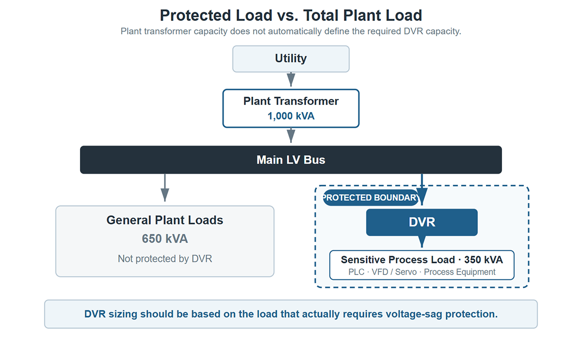
This does not automatically mean that a 1,000 kVA DVR is required. If only semiconductor process equipment, PLCs, VFDs, servo systems, control systems, or selected production equipment require protection, the DVR rating should typically be evaluated around that protected section. The system topology, load growth allowance, operating margin, and possible load transfers still need to be considered before a final rating is selected.
Clearly defining the protected-load boundary affects the DVR power rating, current path, switchgear, cabling, overload margin, cabinet quantity, and final quotation. Marking the proposed boundary on the single-line diagram is preferable to listing the transformer size alone.
5. Actual Operating Load and Load Rate
Provide the actual operating load, because equipment nameplate capacity is not necessarily the load the DVR will continuously carry. A protected group with a 500 kVA combined nameplate rating may, for example, normally operate at 300–350 kVA.
Useful operating data includes:
- normal operating kW and kVA;
- average load rate;
- measured current by phase;
- peak operating load; and
- the maximum expected condition after planned expansion.
This information affects continuous-current selection, inverter utilization, thermal design, overload margin, and the real energy required during support. Measured kW, kVA, power factor, and current trends are more useful than an estimated percentage alone. The nameplate value should still be provided so that the supplier can review possible maximum demand and confirm that the proposed DVR is not based only on a temporary low-load measurement.
6. Load Type
Describe the equipment connected to the protected bus and identify the main load categories. Examples include semiconductor process equipment, VFDs, servo drives, CNC machines, motors, rectifiers, UPS inputs, automation lines, control systems, resistive loads, inductive loads, and other non-linear loads.
Load type matters because different equipment can present different current waveforms, inrush behavior, overload demand, power factor, harmonic content, transient response, and undervoltage tolerance. These characteristics influence the current and inverter margin, control behavior, overload capability, sensing, and protection settings.
If several load types share one protected bus, provide an approximate kW or kVA breakdown rather than naming only the largest item. Also identify equipment that cycles, starts frequently, regenerates energy, or changes load rapidly.
7. Motor Load Percentage
State the percentage of the protected load associated with motors. Also provide the rating of the largest motor, its starting method, and whether any motor is expected to start while the DVR is supporting the load.
Large motors, direct-on-line motors, VFD-fed motors, and servo systems can create different transient-current and dynamic-load requirements. A motor that is already running through a sag presents a different duty from a motor commanded to start during inverter support. The starting method, acceleration profile, simultaneous starting sequence, and mechanical load can therefore affect inverter sizing, current margin, overload capability, and protection settings.
No single universal motor multiplier should be assumed. The motor schedule and operating sequence provide a better basis for engineering than motor percentage alone.
8. Voltage Sag Depth and Residual Voltage
Provide either the maximum voltage-sag depth or the minimum residual voltage that the DVR must support, and state clearly which term is being used. Sag depth is the percentage of nominal voltage that is lost; residual voltage is the percentage that remains during the event.
The relationship is:
Sag Depth = 100% − Residual Voltage
Examples:
| Sag Depth | Residual Voltage |
|---|---|
| 20% | 80% |
| 50% | 50% |
| 70% | 30% |
| 100% | 0% |
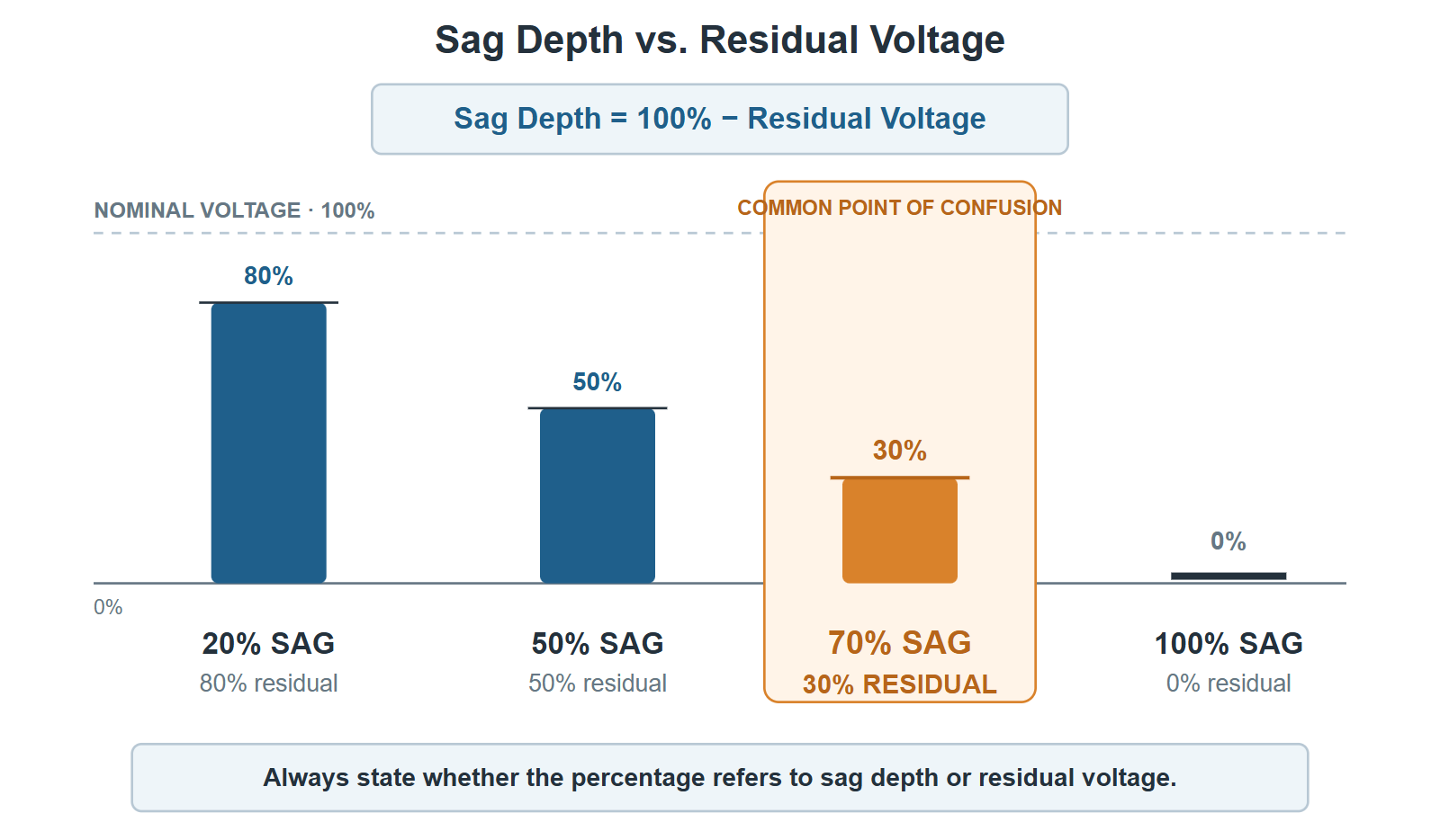
A “70% sag” is therefore not the same as “70% residual voltage.” A 70% sag leaves 30% residual voltage. This distinction should be written explicitly in the DVR RFQ because reversing the terms can result in a substantially different configuration.
As a sag becomes deeper, the DVR generally has to provide a larger share of the load voltage and power from its inverter and stored-energy system. The specified minimum residual voltage therefore affects compensation duty, inverter demand, energy storage, current margin, and final pricing. If measurements are available, provide the residual voltage by phase rather than only a single summary value.
9. Sag Duration
Provide the maximum measured or design voltage-sag duration, together with the corresponding sag depth. Sag depth alone is not enough because the energy requirement depends on how long the disturbance continues.
For example, a 500 kVA load exposed to a 70% sag for 200 ms presents a very different storage duty from the same load exposed to a 70% sag for 5 s. A short, deep sag may require a different design from a shallower sag that lasts much longer.
Sag duration directly affects the required stored energy, thermal duty, and cabinet configuration. When reviewing event records, do not submit only the longest duration and deepest sag as unrelated values. If possible, provide representative depth-duration pairs so the supplier can identify the actual design case.
10. Sag Type
State whether recorded or expected events are single-phase, two-phase, three-phase, or unbalanced voltage sags. Include the affected phases and phase-to-phase or phase-to-neutral measurements used by the recorder.
Sag type matters because the number of affected phases and the degree of unbalance influence voltage detection, phase control, current distribution, protection logic, and restoration strategy. A three-phase event does not necessarily impose the same control duty as a single-phase or strongly unbalanced event of the same reported residual voltage.
If the event type is uncertain, provide the power quality recorder waveform and RMS trend. The supplier can then review the affected phases and measurement basis instead of relying on a broad event label.
11. Event Frequency
Provide the number of sag events per day or other useful period, the minimum interval between events, the typical pattern, and whether events occur in clusters. One event per day is a different operating pattern from several disturbances occurring within a short interval.
Event frequency affects the time available to replenish stored energy and the assessment of repeated-event capability. It can influence energy-storage margin, charging configuration, thermal duty, and the assumptions used in the quotation. Repeated protection should not be treated as unlimited; the acceptable event sequence depends on sag depth, sag duration, protected load, support duty, and recovery time between events.
Where records exist, provide timestamps for a representative period rather than only an annual event count. This makes clustered disturbances easier to identify.
12. Required Ride-Through / Support Duration
State how long the protected load must be supported after the DVR responds. This required support duration is a product configuration requirement and should be distinguished from the measured sag duration.
For example, a site may record an 800 ms sag but require at least 1 s of DVR support to provide design margin. Conversely, a process may only need enough time to complete a controlled sequence. The requirement should be based on the process tolerance, recorded disturbance profile, and project protection objective.
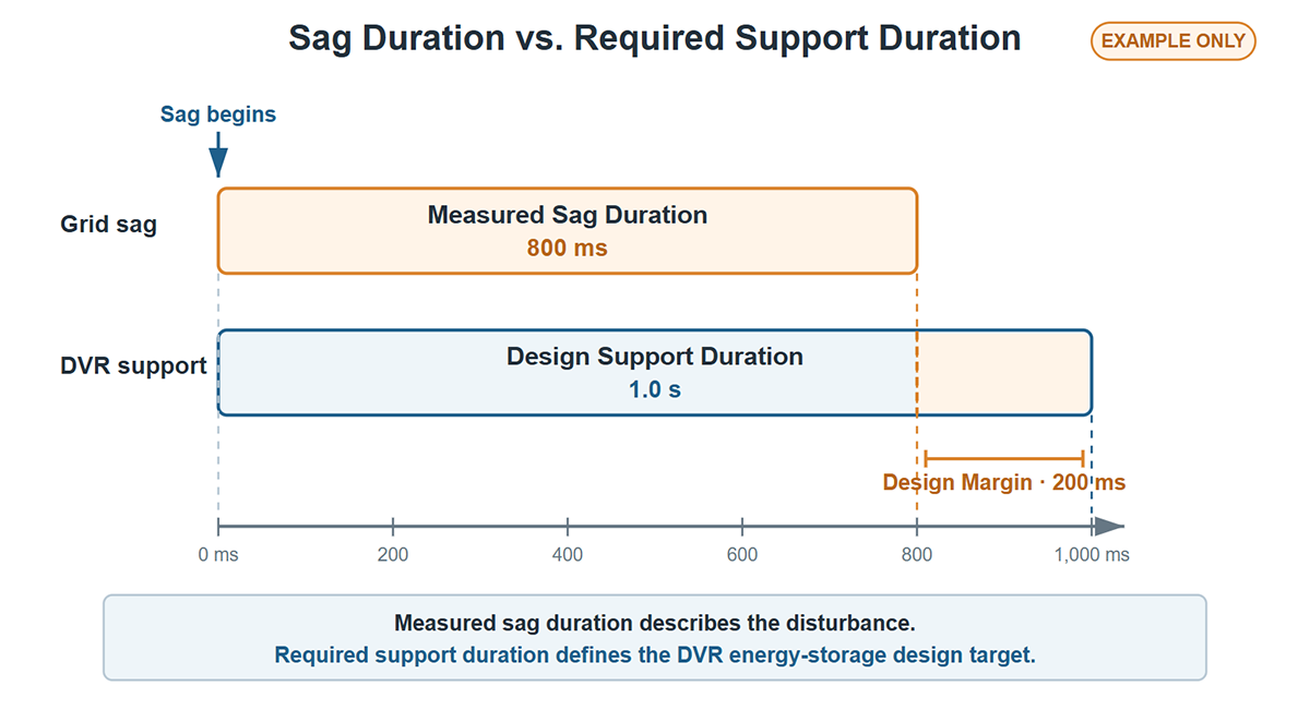
Required support duration directly affects energy-storage sizing, physical cabinet arrangement, charging duty, and project cost. It should be specified together with protected load and minimum residual voltage; a duration value without those conditions is incomplete.
13. Site Environment
Provide the ambient temperature range, installation altitude, indoor or outdoor location, humidity conditions, required ingress-protection level, and relevant installation-room conditions. Also identify dust, condensation, corrosive atmosphere, restricted ventilation, limited access, or space constraints where applicable.
High ambient temperature and high altitude may require derating or changes to cooling and enclosure design. Outdoor installation, humidity, dust, and room ventilation can also affect cabinet protection, heat rejection, clearances, and maintenance access. These factors influence the cabinet configuration and final quotation even when the electrical rating is unchanged.
Do not describe the site only as “normal.” Provide the project design values or the facility’s measured conditions so that environmental assumptions can be recorded in the proposal.
14. Single-Line Diagram and Power Quality Records
Provide the electrical single-line diagram and available power quality records as early as possible. Recommended records include sag waveforms, event logs, RMS trends, voltage by phase, load current, kW, kVA, power factor, and event timestamps.
These documents help verify:
- the actual protected-load boundary;
- nominal voltage, phase arrangement, grounding, and system topology;
- normal, peak, and unbalanced load current;
- sag depth and minimum residual voltage;
- sag duration and affected phases; and
- event frequency and clustering.
The single-line diagram also helps identify transformers, generators, bypass paths, existing protection, downstream distribution, and the practical DVR connection point. Power quality records reduce the risk of selecting a configuration from assumptions or from one incomplete event description. If all requested parameters are not yet available, the diagram and raw recorder export are often the most useful starting documents.
Example: Why “500 kVA DVR” Is Not Enough
Consider the initial request:
Please quote a 500 kVA DVR for a 400 V system.
This gives a nominal capacity and voltage, but it does not define the operating current profile, load behavior, compensation depth, stored-energy duty, wiring, event repetition, or installation environment. It is therefore not enough for an accurate DVR quotation.
A more complete request could state:
| RFQ Item | Project Information |
|---|---|
| System voltage | 400 V |
| Frequency | 50 Hz |
| Phase | 3-phase |
| Protected load | 500 kVA |
| Normal operating load | 380–420 kVA |
| Load type | Semiconductor process equipment with VFD and servo loads |
| Minimum residual voltage | 30% |
| Maximum sag depth | 70% |
| Maximum sag duration | 1 s |
| Sag type | Three-phase, with occasional single-phase events |
| Event frequency | Less than 5 events per day |
| Required support duration | 1 s |
| Environment | Indoor, standard industrial room |
| Single-line diagram | Available |
| Power quality records | Available |
With this information, engineering can begin to determine the DVR power stage, continuous and transient current requirements, inverter rating, supercapacitor storage, support duration, protection settings, and cabinet configuration. The single-line diagram and power quality data would then be reviewed to confirm the assumptions before the final quotation is issued.
The example is still not a universal specification. Wiring details, measured kW and kVA, motor content, peak load, ambient temperature, altitude, and the interval between events should also be confirmed for final selection.
DVR RFQ Checklist
Copy the following checklist, complete the available fields, and send it to the DVR supplier with the single-line diagram and power quality records.
System Voltage:
Frequency:
Phase / Wiring:
Protected Load Capacity:
Actual Operating Load:
Peak Load:
Load Type:
Motor Load Percentage:
Largest Motor Rating:
Minimum Residual Voltage:
Maximum Sag Depth:
Maximum Sag Duration:
Sag Type:
Event Frequency:
Minimum Interval Between Events:
Required Support Duration:
Ambient Temperature:
Installation Altitude:
Indoor / Outdoor:
IP Requirement:
Single-Line Diagram Available: Yes / No
Power Quality Record Available: Yes / No
Additional Notes:
When both sag depth and residual voltage are entered, check that they are consistent. Also state the unit for every capacity, time, temperature, and altitude value.
What We Use This Information For
Each RFQ item supports a specific part of the DVR selection and engineering review.
| Information | Main Engineering Purpose |
|---|---|
| System voltage | Current level and power-stage configuration |
| Protected load capacity | DVR power rating and protected-load boundary |
| Actual operating load | Continuous current, utilization, and operating margin |
| Load type and motor content | Transient, inrush, overload, and control assessment |
| Minimum residual voltage | Required compensation depth and inverter duty |
| Sag duration | Event energy requirement |
| Required support duration | Energy-storage sizing and cabinet arrangement |
| Event frequency | Recharge and repeated-event assessment |
| Phase and wiring | Sensing, switching, neutral, and protection configuration |
| Site environment | Derating, enclosure, cabinet, and cooling requirements |
| Single-line diagram and power quality record | Verification of topology, load, and disturbance data |
These inputs are reviewed together. No single row, including protected-load kVA, is sufficient to establish the complete DVR configuration.
Conclusion
A DVR quotation should not be based on kVA alone. At minimum, provide the system voltage, protected-load capacity, actual operating load, load type, minimum residual voltage, sag duration, and required support duration.
The most accurate DVR selection also uses phase and wiring details, motor information, event frequency, site conditions, a single-line diagram, and measured power quality data. If every parameter is not yet available, provide the available power quality records and single-line diagram first. They give the supplier a practical basis for identifying missing information and preparing a technically sound DVR RFQ.
Related Product
Dynamic Voltage Restorer (DVR): Winzpower DVR systems provide voltage-sag compensation for sensitive industrial loads, with configurations selected from the protected load, sag depth, residual voltage, and required support duration.


