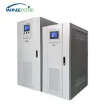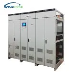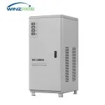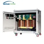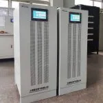



IGBT Static Automatic Voltage Stabilizer
Voltage and Frequency Stabilization for Global Power Systems
Rated Capacity: 3–3000 kVA
Input Voltage: 380 / 440 / 480 Vac; other ratings customizable
Input Frequency: Configurable for 50 / 60 Hz and 400 Hz systems
Output Voltage: Configurable to equipment requirements
Output Voltage Accuracy: ±1%
Output Frequency Stability: <0.1%
Output Frequency: 50 / 60 / 400 Hz, according to configuration
Galvanic Isolation: Standard output isolation transformer
Dynamic Response Time: 2 ms under specified test conditions
WPZ IGBT Static Voltage Stabilizer Overview
The Winzele WPZ series is an IGBT-based static voltage stabilizer designed for critical equipment and processes requiring precise voltage regulation, stable frequency and fast dynamic response. Its AC–DC–AC architecture supplies controlled AC output within the specified input operating range, helping sensitive equipment operate under fluctuating supply conditions.
Typical applications include precision manufacturing, medical electronic equipment testing, aviation equipment and installations supplied by small hydropower systems or remote distribution networks. Each configuration is selected according to the actual supply conditions, load characteristics and required output performance.
The WPZ series can be configured for different input and output voltage ratings, covering worldwide 50 Hz and 60 Hz power systems and 400 Hz aviation power applications. Its primary purpose is to maintain a stable supply for the connected equipment. Voltage and frequency adaptation are available where the site supply and equipment requirements differ.
Real-World Application
200kVA IGBT Stabilizer for Precision Electronics Factory in Vietnam
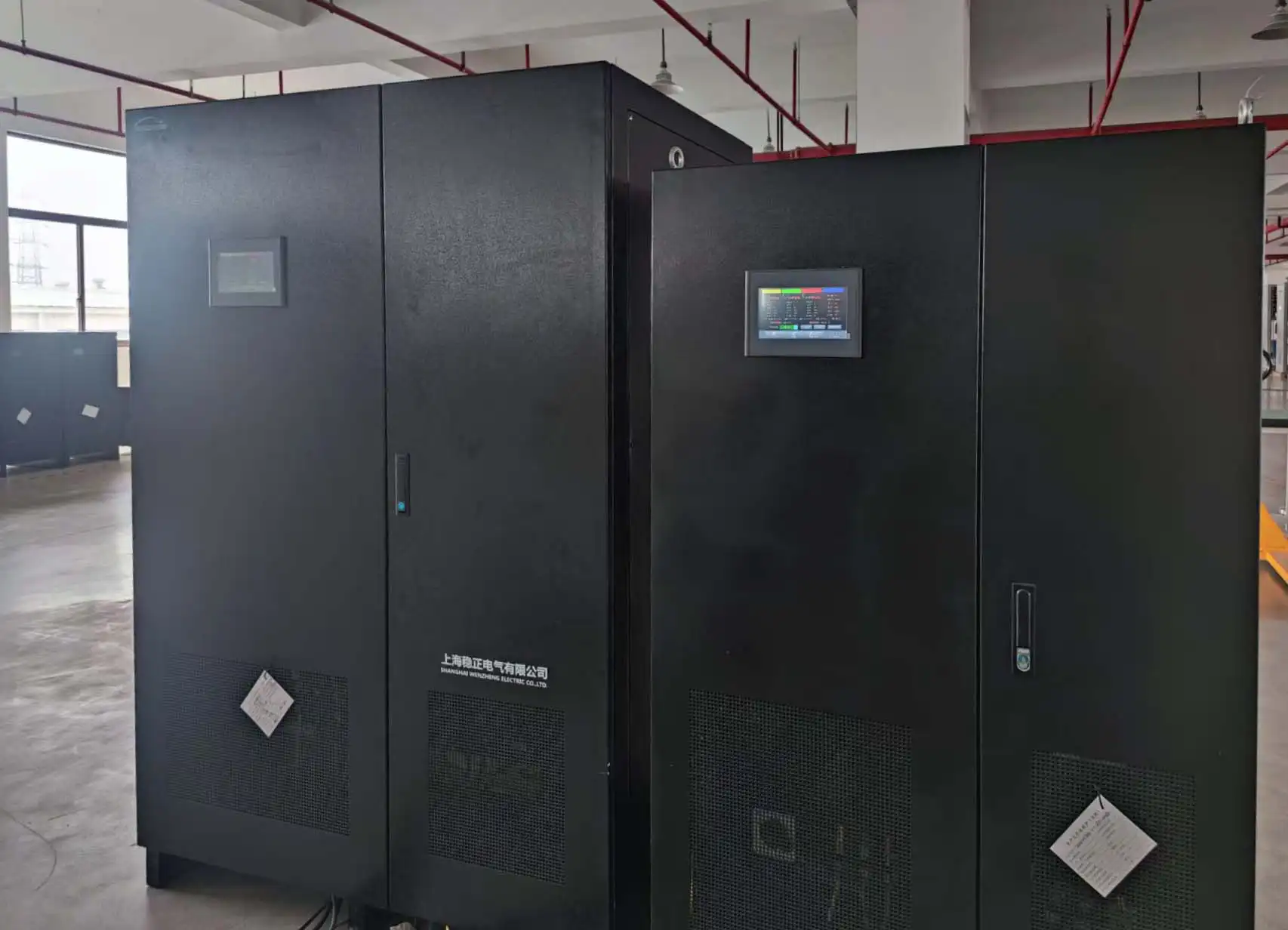
WINZPOWER manufactured and supplied a 200kVA WPZ33200 IGBT Static Automatic Voltage Stabilizer for DONGKWANG COMPANY LIMITED’s precision electronics facility in Vietnam. The system was selected to provide a stable 380V / 50Hz supply where the site grid showed both voltage fluctuation and frequency deviation.
Input:380V±20%, 47–63Hz→Output:380V±1%, 50Hz
How the WPZ Voltage and Frequency Stabilizer Works
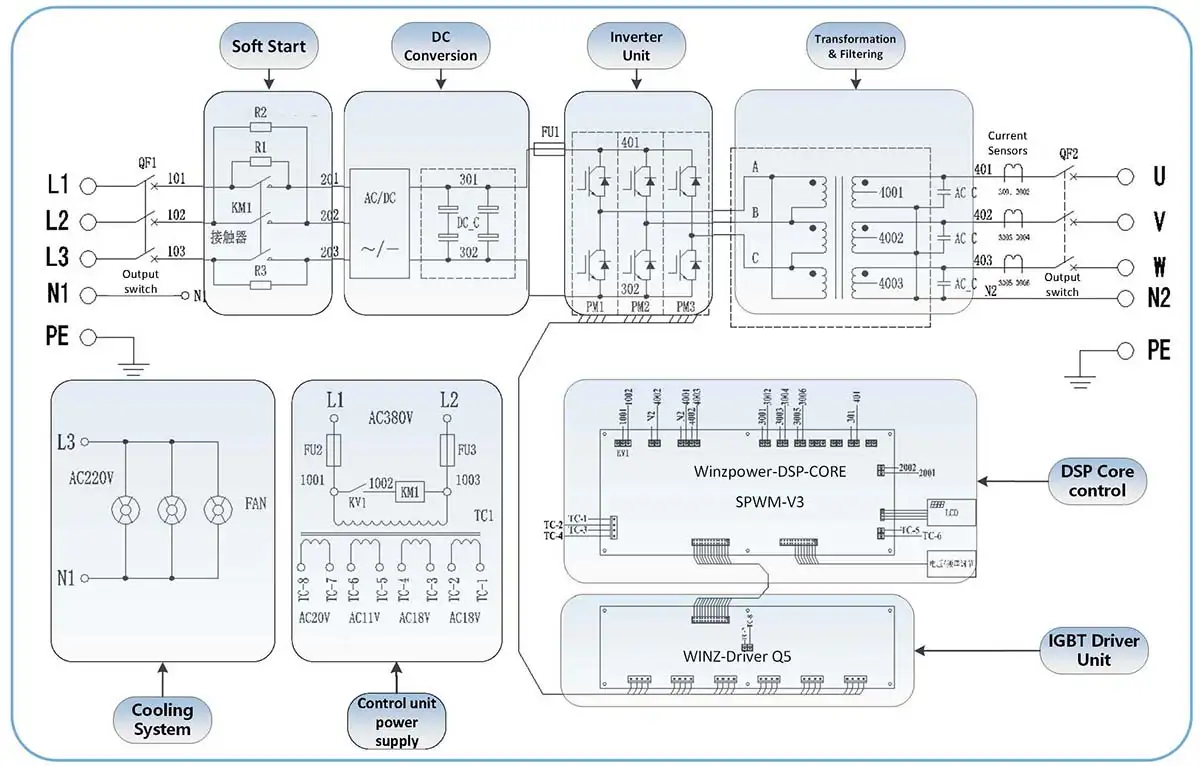
The WPZ series uses an AC–DC–AC power conversion process. Incoming AC power is rectified to a DC link, then an IGBT inverter generates an AC output controlled to the required voltage and frequency.
AC Input → Rectifier → DC Link → IGBT Inverter → Regulated AC Output
1. AC–DC Rectification
The input rectifier converts incoming AC power into DC power. The rectifier configuration and input ratings are selected to match the project’s supply voltage, frequency and capacity requirements.
2. DC-Link Energy Buffering
DC-link capacitors smooth the DC bus voltage and provide a short-term energy buffer between the rectifier and inverter. Working together with the inverter control system, this buffering supports rapid output regulation during input disturbances.
3. IGBT Inversion and Output Regulation
The inverter uses pulse-width modulation to generate the required AC output. Closed-loop voltage and current control adjusts inverter operation to maintain the specified output voltage, while frequency control maintains the selected output frequency within its stated tolerance.
The WPZ series specifies a 2 ms dynamic response to input-voltage changes under the applicable test conditions. This response-time specification is distinct from the time required for the output to settle within its stated voltage tolerance.
4. Output Isolation Transformer
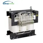
The inverter supplies the load through a dedicated output isolation transformer. This transformer provides galvanic isolation and forms part of the configured output voltage arrangement. Its voltage ratio, capacity and operating frequency are matched to the selected WPZ configuration, including 50 Hz, 60 Hz or 400 Hz applications.
5. Input Harmonic Management
Rectifier selection also affects the harmonic current drawn from the supply. Depending on project requirements, the standard 6-pulse arrangement can be replaced with a 12-pulse or 18-pulse configuration. Active rectification and filtering options are also available. These options address input-side harmonic performance, which is specified separately from output voltage waveform distortion.
WPZ Control Principle Diagram
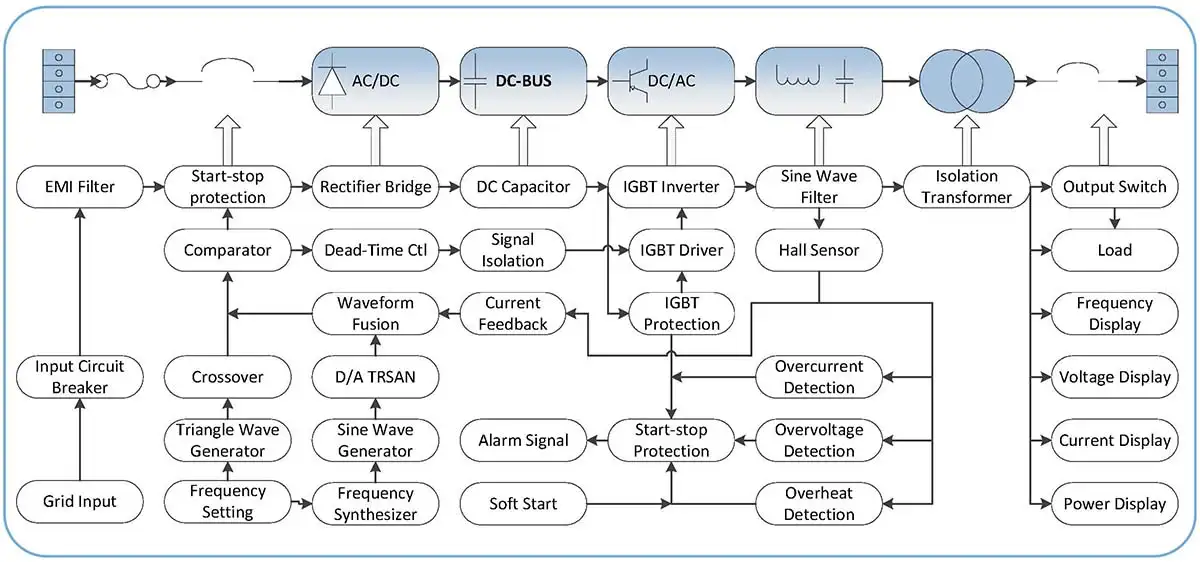
WPZ AC–DC–AC Power Circuit Topology
Inside the WPZ IGBT Static Voltage Stabilizer
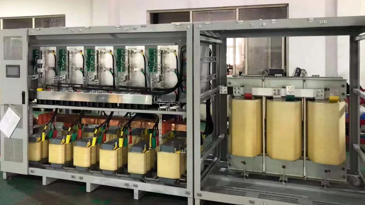
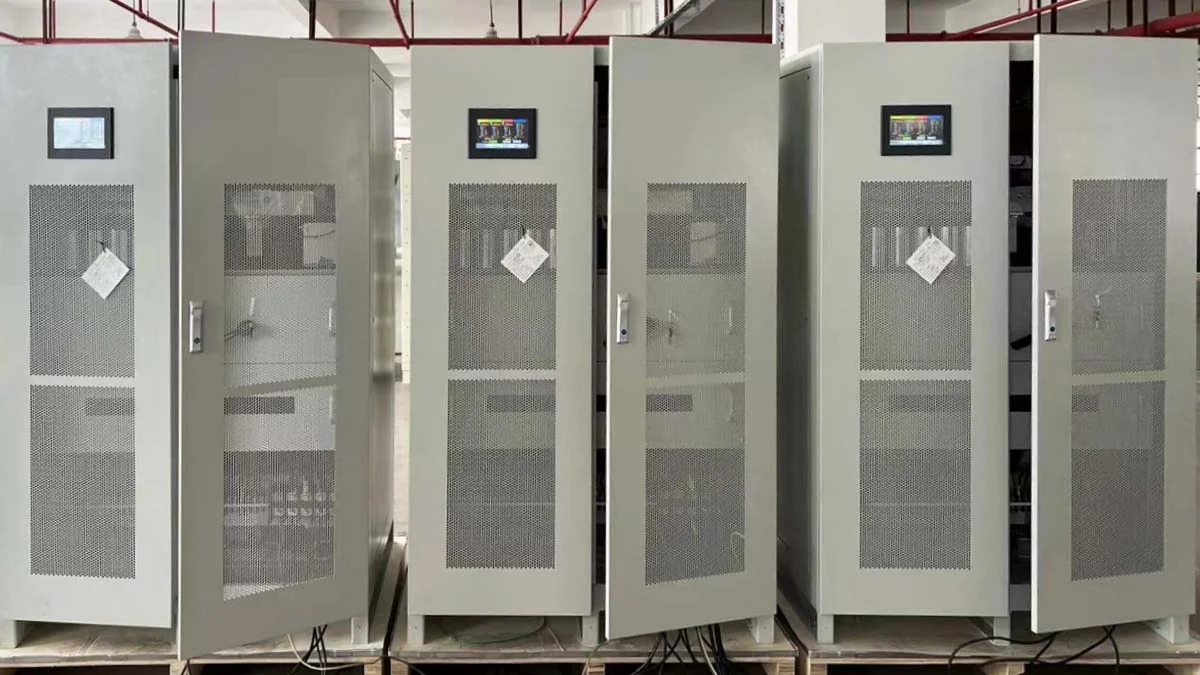
The WPZ series is built around a rectifier, an IGBT inverter and an output isolation transformer, housed in a steel cabinet with front-panel controls and metering. The photographs below show these assemblies inside WPZ cabinets during production and final assembly.
Power Modules and Output
Isolation Transformer
Transformer
Internal Components
Transformer and Magnetic Components during Assembly
Unit Powered On with Displays Active
WPZ Technical Specifications
Input Specifications
| Parameter | Specification |
|---|---|
| Rated Input Voltage | Three-phase: 200 / 208 / 220 / 380 / 400 / 440 / 480 Vac. Single-phase: 110 / 220 / 230 / 380 Vac. Other input voltages can be configured according to project requirements. Three-phase connection: 3-wire (L1, L2, L3) + PE or 4-wire (L1, L2, L3, N) + PE. Single-phase connection: L + N + PE. The connection configuration is selected according to the power system and project requirements. |
| Input Voltage Range | Standard: rated voltage ±15% (e.g., 380 Vac ±15%). Optional ranges: ±20%, ±30% or ±40% of the rated voltage, according to project requirements. |
| Input Frequency Range | Standard: 40–79 Hz. Other input frequency ranges can be configured for specific applications. |
Output & Regulation Performance
| Parameter | Specification |
|---|---|
| Inverter Modulation | IGBT-based inverter with SPWM (Sinusoidal Pulse Width Modulation) |
| Rated Output Voltage | Standard rated output: three-phase 380 Vac or single-phase 220 Vac. The rated output voltage is configured according to the connected equipment and project requirements and maintained within the specified regulation accuracy. Other rated output voltages can be configured, for example: 200 / 400 / 480 / 690 / 800 / 1000 / 3000 / 3300 Vac. Example: 380 Vac output with ±1% regulation accuracy. |
| Output Voltage Accuracy | ±1% average regulation accuracy. Higher accuracy can be configured where required. |
| Dynamic Response Time | <2 ms relative to AC input voltage variation |
| Output Voltage Waveform Distortion | <2% with linear load |
| Rated Output Frequency | Fixed 50 Hz, 60 Hz or 400 Hz, according to the application |
| Frequency Stability | <0.1% |
| Phase Offset | With a balanced three-phase load or no load: ≤±1°; with a 100% unbalanced three-phase load: ≤±4° |
| Three-Phase Voltage Balance | Automatic three-phase voltage balance control |
Control & Communication
| Parameter | Specification |
|---|---|
| Control Mode | Fully digital control. Analog circuitry is used for input and output signal conditioning. |
| Main Control Unit | DSP (TI28XX) for control and measurement. Some models use an ARM main controller with DSP functionality. |
| Control Strategy | SPWM (Sinusoidal Pulse Width Modulation) |
| Switching Frequency | 4–16 kHz, depending on the power rating |
| Voltage and Current Measurement | True RMS sampling with three-phase synchronization. 256-point sampling for RMS and FFT. |
| Voltage, Current and Frequency Control Strategy | PID dual closed-loop control |
| Communication Interfaces | RS-485 / RS-232 with Modbus RTU protocol. Optional TCP/IP, GPRS and other interfaces. |
Display & Monitoring
| Parameter | Specification |
|---|---|
| Display | Industrial touchscreen (7 or 10 inches). Other LCD sizes can be configured according to project requirements. |
| Displayed Electrical Parameters |
Three-phase input voltage and input frequency; Three-phase output line voltage and output frequency; Average output line voltage; Output power factor; three-phase output current; Output active power and apparent power; Heat sink temperature. |
| Displayed Alarm Information | Input overvoltage (OV); overcurrent (OC); input undervoltage (UV); IGBT fault; heat sink overtemperature; transformer overtemperature; and other fault information. |
| Display Accuracy | Class 0.5s |
| Voltage Display Resolution | 0.1 V |
| Current Display Resolution | 0.1 A |
Protection
| Parameter | Specification |
|---|---|
| Protection Functions | Input overvoltage (OV); overcurrent (OC); input undervoltage (UV); IGBT fault; heat sink overtemperature; transformer overtemperature; and short circuit. |
| Protection Action | Output shutdown and alarm. Fault dry contacts can be configured (NC and NO). |
| Please contact Winzele to discuss other specific requirements. | |
List of WPZ Power Models & Products
1.Three-phase Model List
Small Capacity (3-30 kVA)
| Type | Capacity (kVA) |
Output | Dimension W×D×H(mm) |
| (A) | |||
| WPZ13003 WPZ33003 |
3 | 4.2 | 350×650×670 (Locking Castor Wheel) |
| WPZ13006 WPZ33006 |
6 | 8.4 | |
| WPZ13010 WPZ33010 |
10 | 15 | |
| WPZ13015 WPZ33015 |
15 | 23 | 460×700×1170 (Locking Castor Wheel) |
| WPZ13020 WPZ33020 |
20 | 30 | |
| WPZ33030 | 30 | 45 |
Medium Capacity (45-200 kVA)
| Type | Capacity (kVA) |
Output | Dimension W×D×H(mm) |
| (A) | |||
| WPZ33045 | 45 | 68 | 780×650×1450 |
| WPZ33060 | 60 | 91 | |
| WPZ33075 | 75 | 114 | 950×700×1600 |
| WPZ33090 | 90 | 137 | |
| WPZ33120 | 120 | 183 | |
| WPZ33150 | 150 | 228 | 1200×750×1800 |
| WPZ33200 | 200 | 304 |
Large Capacity (250-800 kVA)
| Type | Capacity (kVA) |
Output | Dimension W×D×H(mm) |
| (A) | |||
| WPZ33250 | 250 | 380 | 1400×800×2000 |
| WPZ33300 | 300 | 456 | |
| WPZ33350 | 350 | 532 | 1500×1050×2000 |
| WPZ33400 | 400 | 608 | |
| WPZ33500 | 500 | 760 | 1500×1050×2000 |
| WPZ33600 | 600 | 912 | |
| WPZ33800 | 800 | 1216 |
Extra-Large Capacity (1000-1800 kVA)
| Type | Capacity (kVA) |
Output | Dimension W×D×H(mm) |
| (A) | |||
| WPZ331000 | 1000 | 1520 | 1500×1050×2000 |
| WPZ331200 | 1200 | 1823 | |
| WPZ331400 | 1400 | 2127 | 1500×1050×2000 |
| WPZ331600 | 1600 | 2431 | |
| WPZ331800 | 1800 | 2735 | 1500×1050×2000 |
Notice:
1. For 90kVA and below, use high and low voltage switch. For 90kVA and above, choose one of the high and low voltage when ordering;
2. The current in the table is calculated when the line voltage is 380V. The actual use should be calculated according to the highest voltage of the selected equipment;
2.Single-phase Model List
Small Capacity (0.5-30 kVA)
| Type | Capacity (kVA) |
Output(A) | Dimension W×D×H(mm) |
| Current | |||
| WPZ11-500W | 0.5 | 2.1 | 425×436×173 |
| WPZ11001 | 1 | 8.4 | |
| WPZ11002 | 2 | 17 | 350×650×670 (Locking Castor Wheel) |
| WPZ11003 | 3 | 26 | |
| WPZ11005 | 5 | 42 | |
| WPZ11010 WPZ31010 |
10 | 84 | |
| WPZ11015 WPZ31015 |
15 | 126 | 460×700×1170 (Locking Castor Wheel) |
| WPZ11020 WPZ31020 |
20 | 168 | |
| WPZ11030 WPZ31030 |
30 | 252 |
Medium Capacity (45-300 kVA)
| Type | Capacity (kVA) |
Output(A) | Dimension W×D×H(mm) |
| Current | |||
| WPZ11045 WPZ31045 |
45 | 378 | 780×650×1450 |
| WPZ31060 | 60 | 504 | |
| WPZ31075 | 75 | 630 | 950*700*1600 |
| WPZ31090 | 90 | 756 | |
| WPZ31120 | 120 | 1008 | 1200×750×1800 |
| WPZ31150 | 150 | 1260 | |
| WPZ31200 | 200 | 1680 | 1400×800×2000 |
| WPZ31300 | 300 | 2700 |
Manufacturing Capability
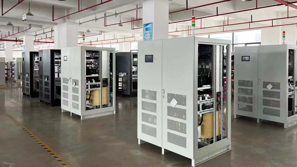
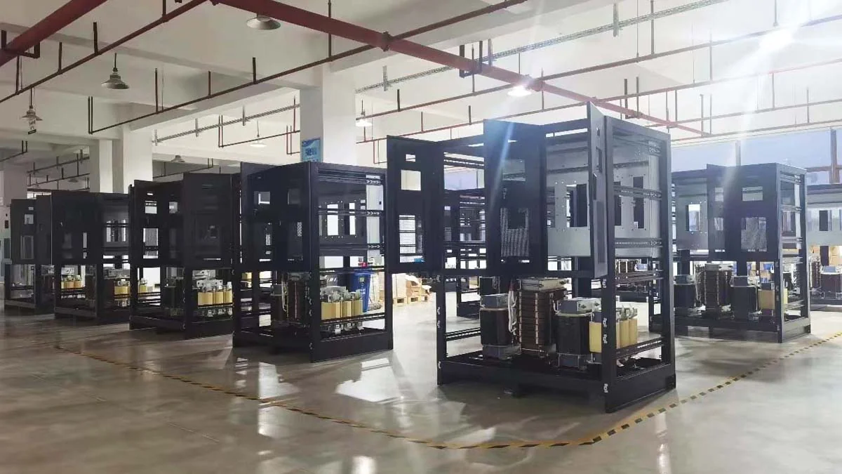
Winzele manufactures the WPZ series in its own production facility. Cabinet assembly, electrical wiring, component integration and final configuration are carried out in-house, so each unit can be built to the customer’s specified input voltage, output voltage, output frequency and capacity.
IGBT Stabilizer Production Line
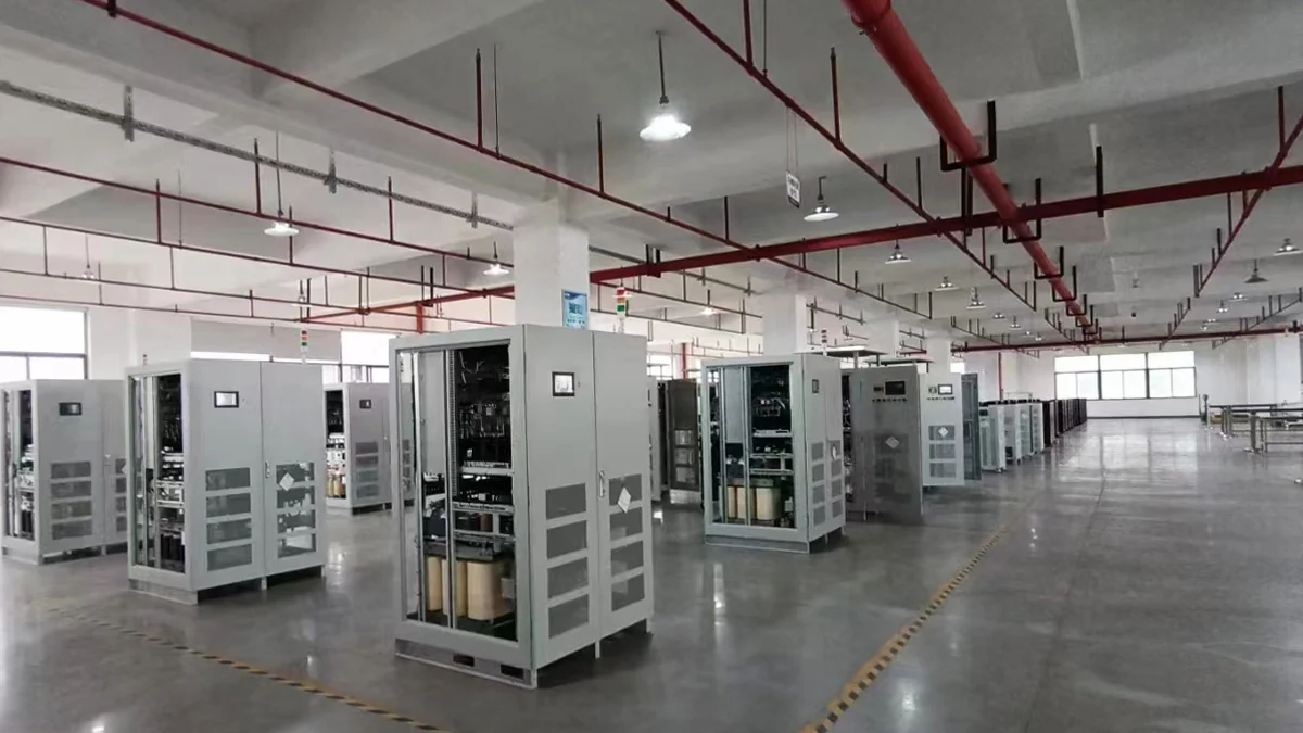
Batch Cabinet Assembly
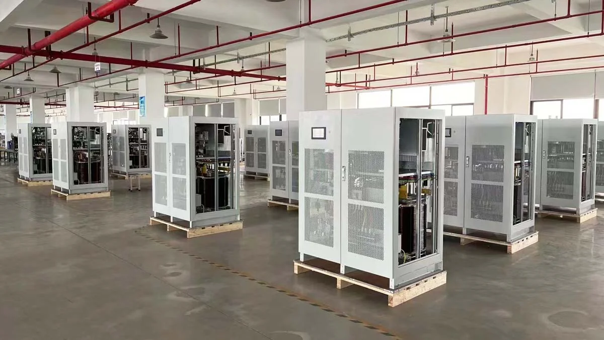
Cabinet Electrical Assembly
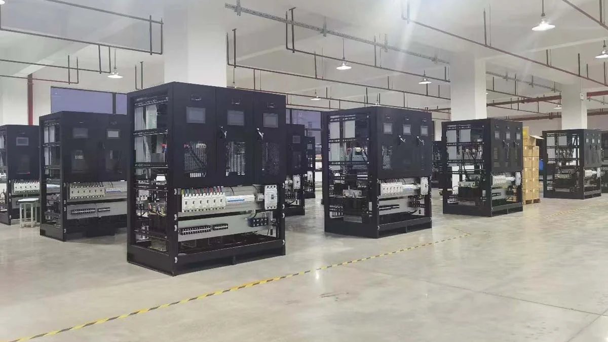
Technicians Working on Cabinets
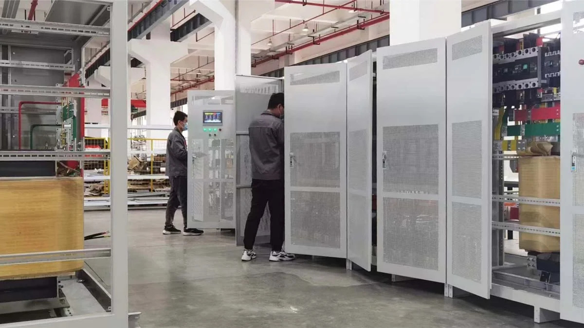
Factory Acceptance Testing
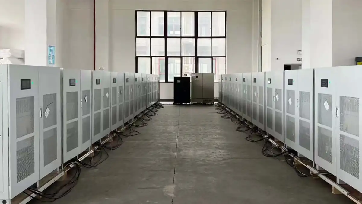
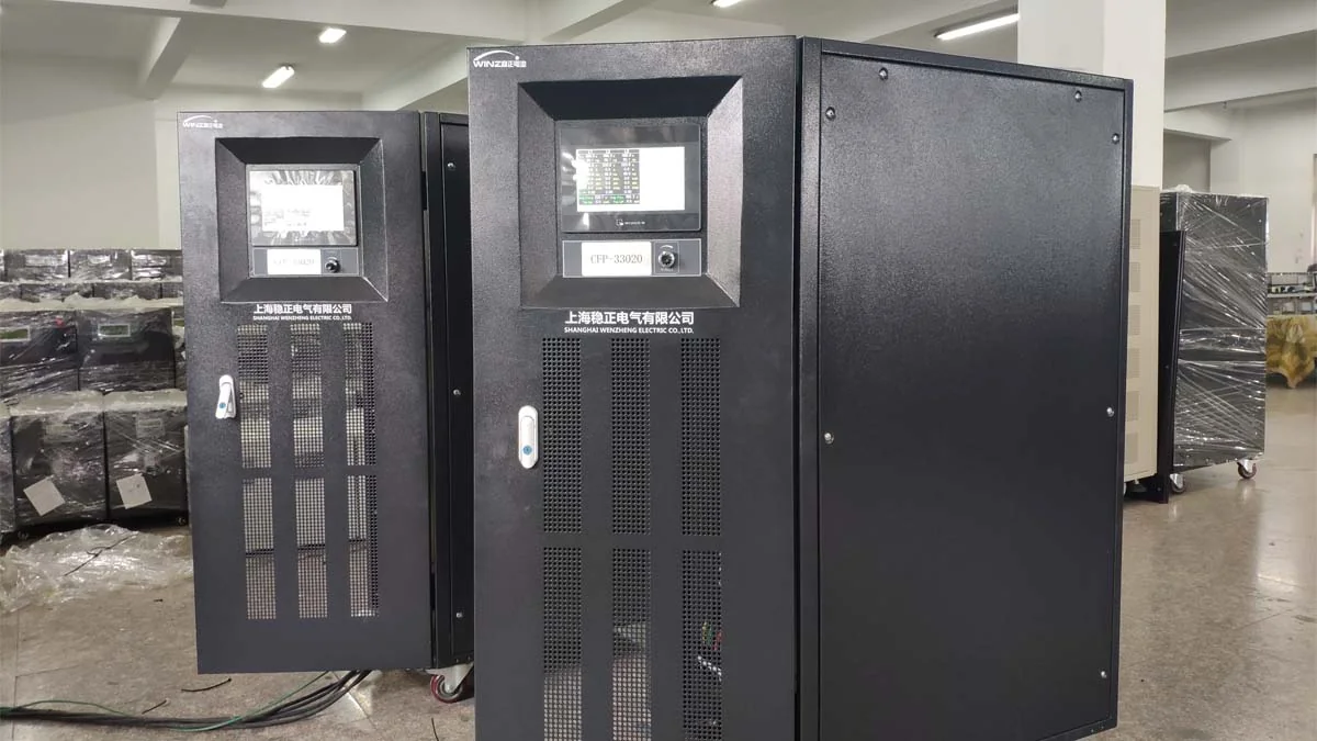
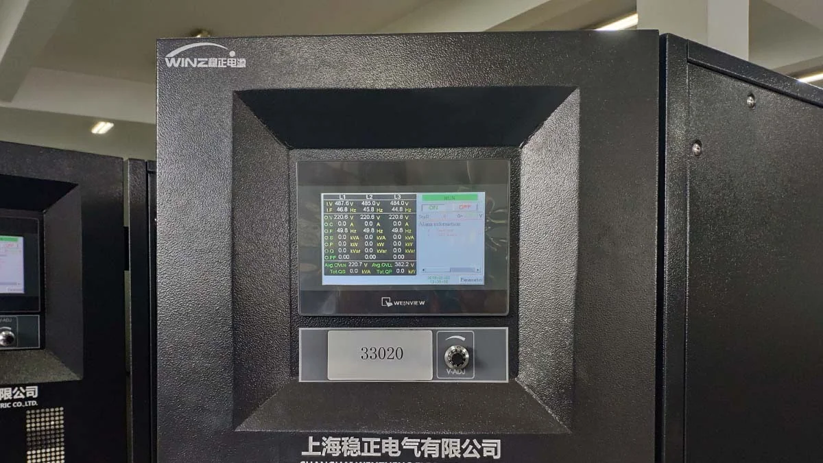
Every WPZ unit is assembled, wired and tested at the factory before shipment. Tests cover the ordered configuration, including inductive load conditions, and the control panel readings are checked against the specified output voltage and frequency.
Factory Acceptance Test
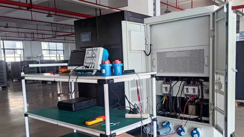
Factory Commissioning and Adjustment
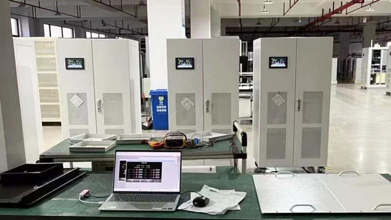
Inductive Load Testing
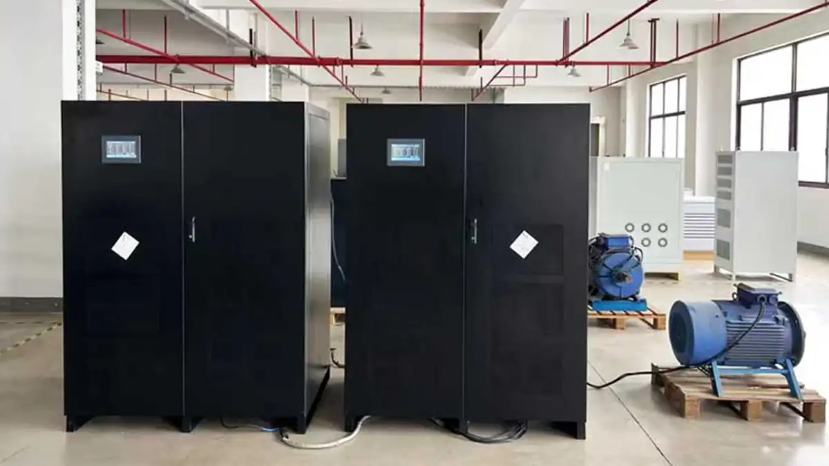
Factory Test Setup Overview
Cabinet Test Units
Control Panel Readings during Testing
Application
1. Railway, aviation, and navigation systems;
2. Precision testing of medical electronic equipment;
3. Power supply for imported electronic and electrical equipment;
4. Testing of exported electronic and electrical products;
5. CNC machine tools, light industry and textiles, and automated production lines;
6. Generator-powered facilities requiring stable voltage and frequency.
Get a Quick Quote
Contact our sales team for pricing, technical specifications, and delivery information.