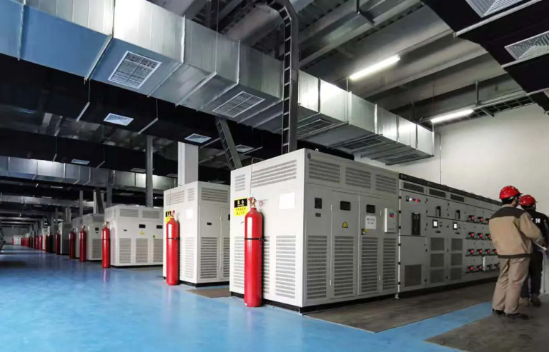
Active Harmonic Filter Solution for Ningxia Monocrystalline Silicon Manufacturing Plant


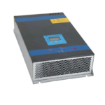
Industrial Active Harmonic Filter (AHF) for harmonic compensation, power quality improvement and stable operation of electrical systems with nonlinear loads.
Rated Current:30A–150A
Voltage:400V / 480V / 690V (Custom)
System:3-phase 3-wire / 4-wire
Compensation:Harmonic + Reactive + Load Balancing
Response:≤5ms
Installation:Rack-mounted / Wall-mounted / Cabinet Integration
Winzele Active Harmonic Filter (AHF) is a dynamic power quality solution designed to compensate harmonic currents generated by nonlinear loads and improve electrical system performance. Winzele manufactures a complete range of active harmonic filters for industrial power systems, covering different rated currents, voltage levels and installation configurations.
Typical applications include variable frequency drives, rectifiers, UPS systems, semiconductor equipment and industrial automation systems. These nonlinear loads may introduce current distortion and affect power quality. The AHF provides real-time harmonic compensation to support stable electrical operation, reduce the risk of equipment malfunction and support compliance with applicable power quality requirements.
The Winzele AHF detects load current through external CTs and provides millisecond-level dynamic response, delivering harmonic compensation, reactive power compensation and three-phase load balancing in one system. Modular installation allows flexible deployment in rack-mounted, wall-mounted or cabinet configurations, simplifying system expansion and maintenance for both new installations and retrofit projects.
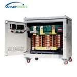
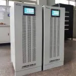
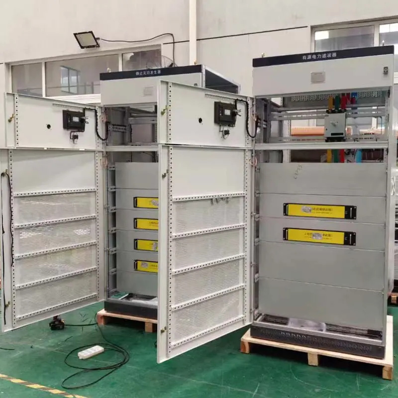
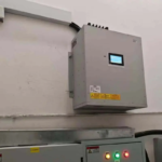
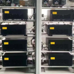
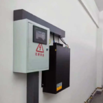
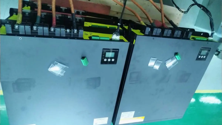
Selected industrial installations using Winzele active harmonic filters to reduce harmonic distortion and improve power quality for nonlinear loads.
Looking for a similar project?
Explore more real installations by equipment, industry and capacity.
| Parameter | Specification |
|---|---|
| Rated Voltage | 200V / 220V / 400V / 480V / 690V |
| Rated Current | 30A / 50A / 75A / 100A / 150A |
| Phase | Three-phase |
| Frequency | 50/60Hz ±10% |
| Wire System | Three-phase three-wire / Four-wire |
| Compensation Capacity | Rated current based |
| Installation Method | Rack-mounted / Wall-mounted / Cabinet Integration |
| Parameter | Specification |
|---|---|
| Harmonic Compensation | Harmonic + Reactive + Load imbalance compensation |
| Harmonic Range | 2nd–51st harmonic |
| Harmonic Compensation Capability | >95%(typical harmonic current compensation) |
| Filtering Performance | THDi ≤5% at rated load |
| Response Time | ≤5ms |
| Switching Frequency | 20kHz |
| Load Balancing | ≤5% |
| Neutral Filtering Capacity | 3× rated current (4-wire system) |
| Overload Capacity | 110% rated current continuous, 120% rated current for 1 minute |
| Target Power Factor | Adjustable from -1.0 to +1.0 |
| Parameter | Specification |
|---|---|
| Circuit Topology | Three-level NPC |
| Control Algorithm | Intelligent FFT + Self-adaptive control |
| Controller | DSP + FPGA |
| Parallel Operation | ≤20 units |
| Redundancy | Independent operation |
| Protection | IGBT hardware + software protection |
| Communication Interface | RS485 / CAN |
| Communication Protocol | Modbus |
| CT Installation Position | Grid / load side |
| CT Installation Mode | Open loop or closed loop (open loop recommended for parallel operation) |
| Human Machine Interface | External 7-inch screen / no screen / 1.8-inch screen (optional) |
| Parameter | Specification |
|---|---|
| Cooling Method | Intelligent PWM fan cooling |
| Protection Level | IP20 |
| Noise | <60dB |
| Color | RAL7035 / RAL9005 |
| Ambient Temperature | -25~55℃ |
| Relative Humidity | ≤95% non-condensing |
| Altitude | ≤3000m |
| Applicable Standard | IEEE 519 (power quality reference) |
| Qualifications | Test report |
Winzele active harmonic filters are available in rack-mounted and wall-mounted configurations to meet different industrial installation requirements. The following mechanical drawings provide reference dimensions, weight information and cabinet integration structure for system planning and installation.
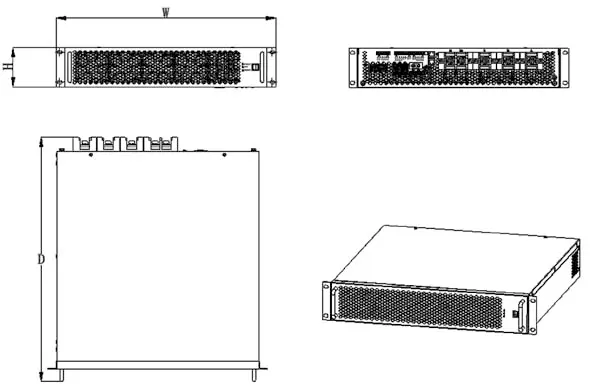
|
AHF Model /Rated Current |
Dimensions(W × H × D, mm) |
Weight |
|---|---|---|
| 30A | 230 × 400 × 88 | 9 kg |
| 50A | 440 × 479.5 × 88 | 14 kg |
| 75A | 440 × 560 × 88 | 17 kg |
| 100A | 500 × 600 × 102 | 27 kg |
| 150A | 500 × 600 × 102 | 30 kg |
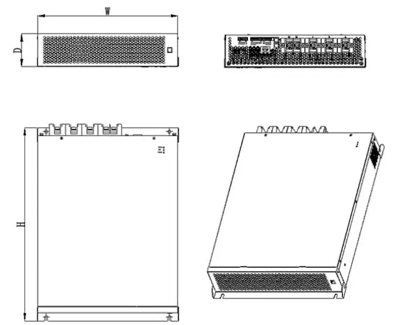
|
AHF Model /Rated Current |
Dimensions(W × H × D, mm) |
Weight |
|---|---|---|
| 30A | 88 × 486.5 × 484 | 11 kg |
| 50A | 88 × 486.5 × 484 | 14 kg |
| 75A | 88 × 571.5 × 484 | 17 kg |
| 100A | 100 × 618 × 544 | 27 kg |
| 150A | 100 × 618 × 544 | 30 kg |
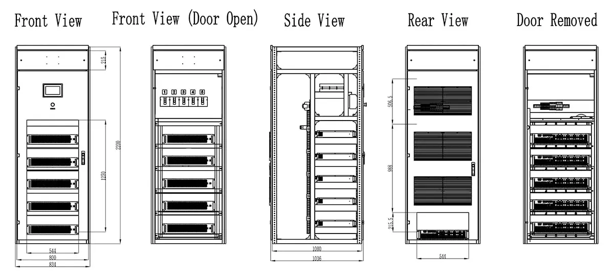
The cabinet structure is designed by Winzele for active harmonic filter system integration. The following recommendations are provided as engineering reference for cabinet assembly, ventilation design and field installation.
The cabinet structure shown above is designed by Winzele and provided for engineering reference.
Proper ventilation design is important for AHF cabinet operation. Cooling fan quantity and ventilation openings should be selected according to cabinet width and module quantity.
The cabinet front and rear doors should use honeycomb ventilation openings to improve internal airflow and heat dissipation.
N represents the number of AHF modules installed in the cabinet.
Maintain sufficient spacing between AHF modules to ensure proper airflow and thermal performance.
Recommended vertical spacing between modules: ≥50mm
Based on Winzele field installation experience, additional front barriers should be avoided whenever possible. Additional blocking plates may increase module enclosure temperature and reduce cooling performance.
The maximum recommended number of modules in one cabinet is 8.
For special projects, up to 9 modules may be installed. However, reduced spacing may affect heat dissipation performance. This configuration should only be considered when the electrical room environment is suitable, such as air-conditioned rooms with annual temperature below 35°C.
The cabinet should include a dedicated current terminal block. CT sampling wires must pass through the terminal block before connection to the AHF/APF/SVG modules to simplify future maintenance and troubleshooting.
The following diagrams illustrate typical installation configurations of active harmonic filters in industrial power distribution systems. Detailed wiring requirements and commissioning procedures are provided in the technical manual.
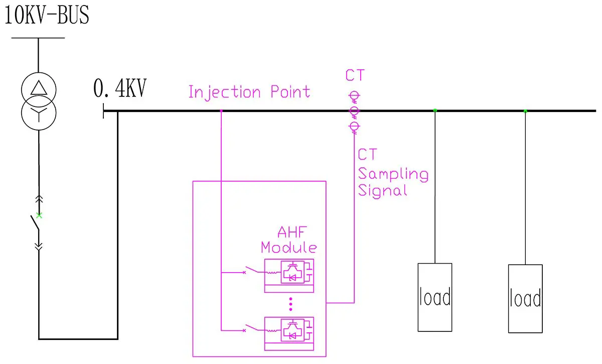
Suitable for individual nonlinear loads or dedicated equipment harmonic mitigation. The AHF detects load current distortion and injects compensation current through the parallel connection point.
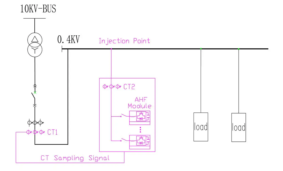
Suitable for industrial power distribution systems with multiple nonlinear loads. The AHF is connected in parallel with the main bus to provide centralized harmonic compensation.
Before delivery, Winzele active harmonic filter systems undergo functional verification and performance checks to ensure reliable operation in industrial power quality applications.
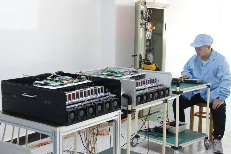
Functional testing verifies the operation of AHF power modules, control systems and protection functions under simulated operating conditions.
Performance verification confirms current detection accuracy, compensation response and harmonic reduction capability according to system requirements.
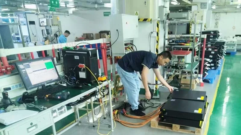
Protection functions and communication interfaces including RS485, CAN and Modbus are checked to ensure reliable integration with industrial control systems.
Final inspection is performed before shipment to confirm product condition, wiring quality and overall system reliability.
Field measurement examples showing voltage/current waveform and harmonic spectrum analysis under industrial power system conditions.
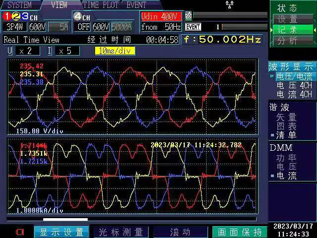
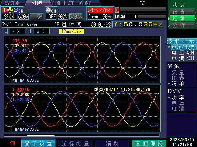
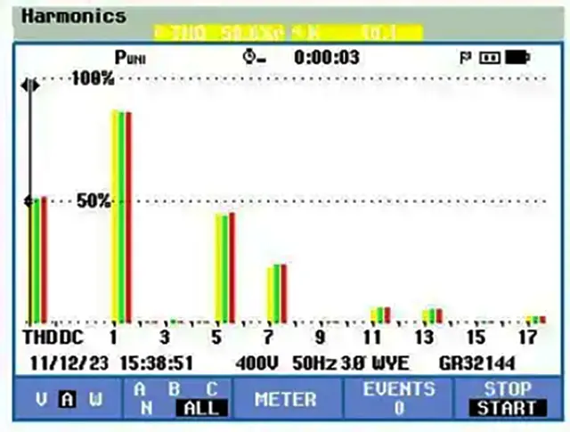
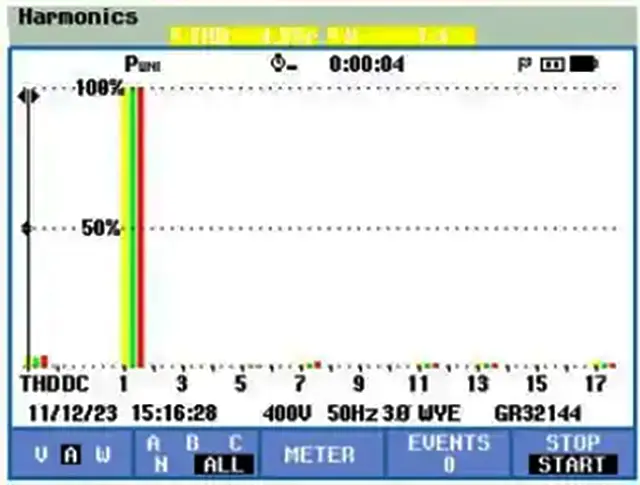
Note: Measurement results are provided as typical field verification examples. Actual harmonic reduction performance depends on load characteristics, system impedance, CT installation and selected AHF capacity.
Contact our sales team for pricing, technical specifications, and delivery information.