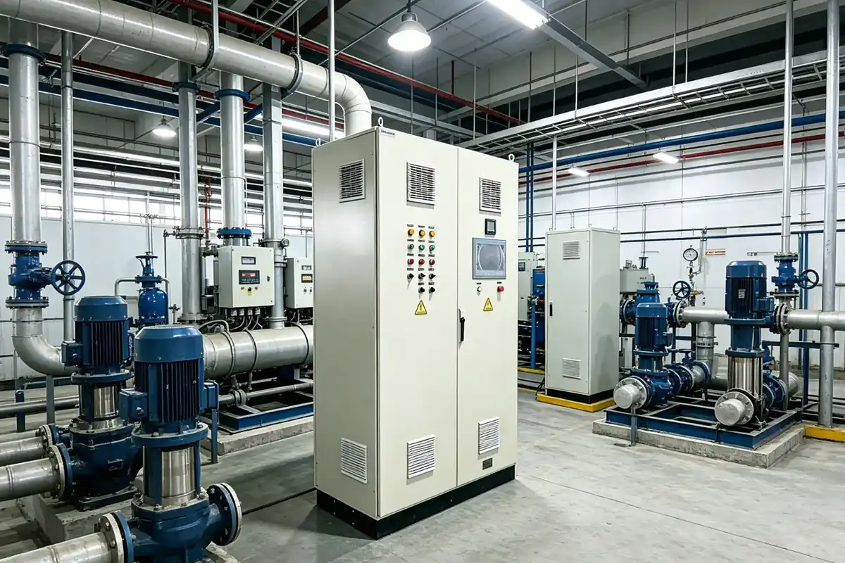
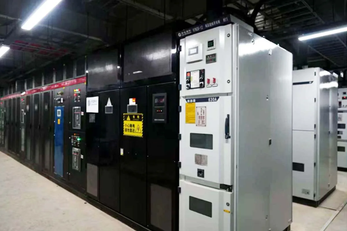
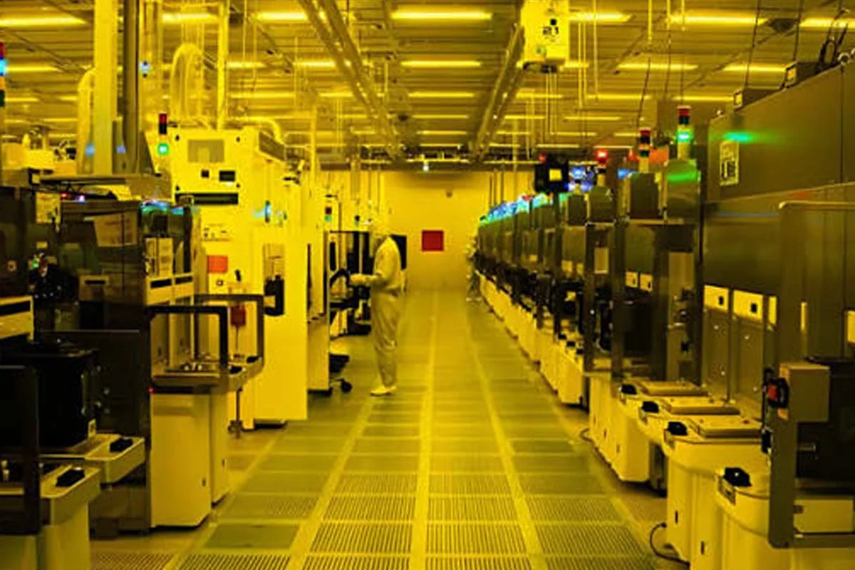
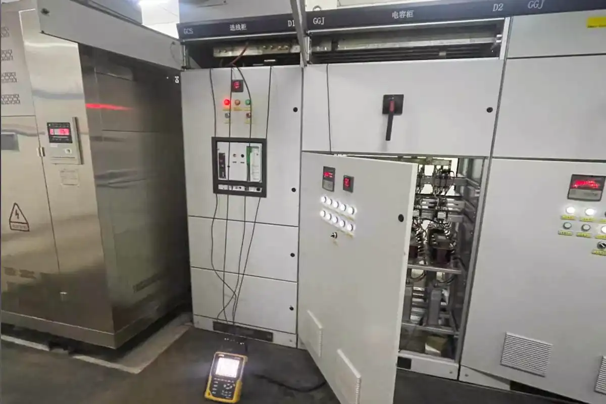
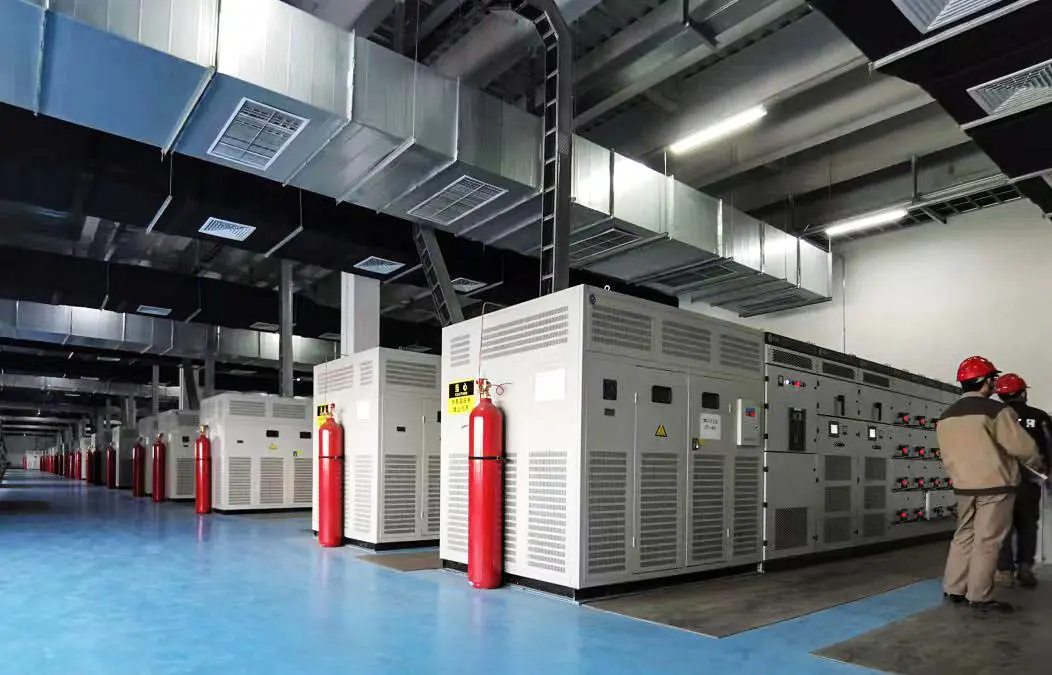
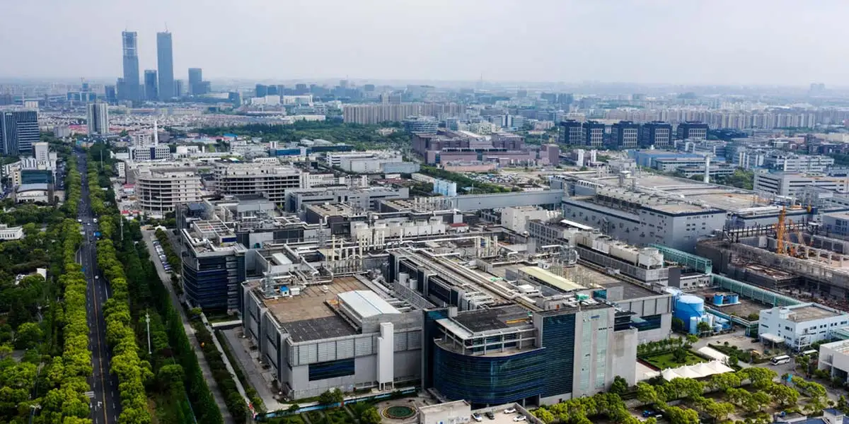
Where Do Harmonics Come From?
Common harmonic sources in industrial facilities include:
Power Quality Solution
Measure, reduce and verify harmonic distortion with an engineered active harmonic filter solution.
01. Decision Path
Harmonic mitigation equipment should primarily be selected based on on-site measurement data. For projects where measurements are not yet available, harmonic current may be estimated from transformer capacity, load factor, the proportion of nonlinear loads and load type for preliminary configuration. The final solution should be verified against on-site data.
02. What Are Harmonics?
Harmonics are not a standalone fault; they are distorted currents generated by nonlinear loads. When large numbers of variable frequency drives, UPS systems, rectifiers, welding machines and similar equipment operate simultaneously, they draw non-sinusoidal current from the grid. As these harmonic currents flow through system impedance, they may cause voltage distortion and affect the operation of the wider distribution system.
Common harmonic sources in industrial facilities include:
This does not indicate a measurement error; it is a common condition in industrial power systems.
When selecting an AHF, we evaluate the complete power distribution system rather than relying on a single THDi or THDv value.
Typical factors include:
For example, depending on the measuring point and system conditions, THDi may reach 25% to 35% while THDv remains around 2% to 4%.
This does not mean the system is free of harmonics; it indicates that lower system impedance limits the resulting voltage distortion.
Voltage sags, outages and long-duration undervoltage require different analysis and are not corrected by an active harmonic filter.
03. Sources and Orders
The actual harmonic spectrum depends on equipment topology, control method, system impedance and operating condition. The values below are typical indicators for assessment, not a substitute for measurement.
Six-pulse front ends commonly prompt checks of the 5th, 7th, 11th and 13th orders.
Switch-mode power supplies and UPS rectifiers can create load-dependent current distortion.
CNC, semiconductor and automated lines combine many switching and rectifier loads.
The source mix and operating cycle must be measured before the required AHF current rating is selected.
| Source | Typical harmonic indication | Assessment notes |
|---|---|---|
| 6-pulse VFD / rectifier | h = 6k +/- 1; commonly 5th, 7th, 11th, 13th | Motor drives, rectifiers and DC bus equipment. |
| UPS and switch-mode power supplies | Low-order and high-frequency components | Common in IT rooms, control rooms and backup systems. |
| Welding equipment | Broad and varying spectrum | Current changes with process stage and duty cycle. |
| Arc furnaces | 3rd, 5th, 7th, 11th, 13th may be prominent | Random fluctuation and flicker can appear with harmonics. |
| LED drivers | Depends on driver topology | Large groups can affect building power quality. |
| Data centers and IT loads | 3rd and 5th are common concerns | Neutral conductor loading should be checked in four-wire systems. |
| Battery chargers | Rectifier-related characteristic harmonics | Charging stage and control method affect spectrum. |
| CNC and automated production equipment | Drive and rectifier related harmonics | Servo drives, VFDs and power supplies may operate together. |
04. Warning Signs and Business Impact
Harmonic problems often appear as heat, nuisance trips, interference and premature equipment failure, but measurement is required before confirming the cause.
Possible signUnexpected temperature rise under normal loading.
VerifyMeasure RMS current, harmonic spectrum and temperature under the same operating condition.
Possible signNeutral current remains high despite reasonably balanced phase loads.
VerifyMeasure neutral RMS current and triplen harmonic components in the three-phase four-wire system.
Possible signRepeated fuse operation, overheating, bulging or abnormal capacitor current.
VerifyCheck the harmonic spectrum, capacitor current and possible resonance conditions.
Possible signProtection devices operate without an obvious sustained overload.
VerifyReview event records and measure RMS current, peak current and waveform distortion.
Possible signIntermittent resets, communication errors or unstable measurement signals.
VerifyCorrelate fault timestamps with load switching and power-quality records.
Possible signAdditional noise, temperature rise or vibration without a clear mechanical cause.
VerifyCheck voltage distortion, current spectrum, load condition and mechanical factors.
05. Measurement and Assessment
AHF selection should begin with measurements taken at the correct locations and under representative load conditions. A single instantaneous THD value is not enough for reliable engineering.
Review the single-line diagram, transformer data, load list and capacitor-bank information before deciding where to measure.
Measure at relevant points such as the PCC, main bus, feeder and critical nonlinear load. Results from different points answer different questions.
Capture light load, normal production, peak load, startup and process cycles together with the measurement time.
Record RMS voltage and current, THDi, THDv, power factor and individual harmonic orders, not only one total THD number.
Compare upstream and downstream measurements to identify dominant loads and distinguish background voltage distortion from load-generated harmonic current.
Define equipment protection, internal power-quality needs, project requirements and any applicable limit at the PCC.
06. Where Should Harmonics Be Mitigated?
The best location depends on whether harmonic current is concentrated at one large source or distributed across several panels and production lines.
Often suitable when one large nonlinear load dominates the harmonic profile.
Often suitable when several nonlinear loads contribute to bus or PCC distortion.
07. Connection and Control Methods
Winzele AHF systems support grid-side or load-side CT installation, open-loop or closed-loop control, three-phase three-wire and three-phase four-wire systems, and parallel module configurations.
08. Winzele Harmonic Mitigation Process
Winzele harmonic mitigation work should move from measurement to engineering selection and commissioning support, then verify the actual result at the agreed measuring point.
Field Engineering
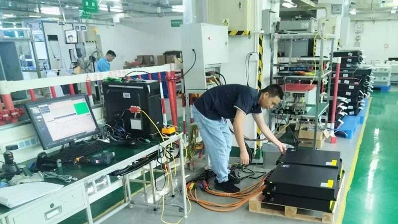
Project photos document harmonic measurement, cabinet retrofit, AHF installation and post-installation verification.
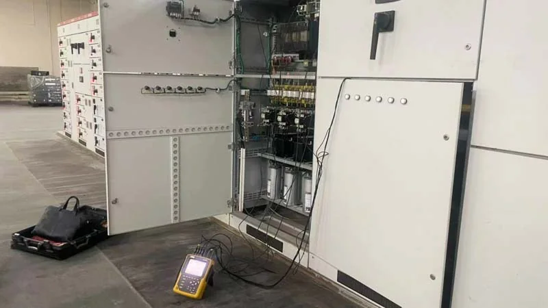
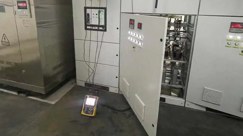
Power-quality analyzer connected during harmonic measurement at industrial distribution equipment.
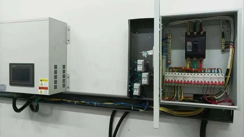
Distribution-panel modifications and secondary wiring prepared for a wall-mounted AHF installation.
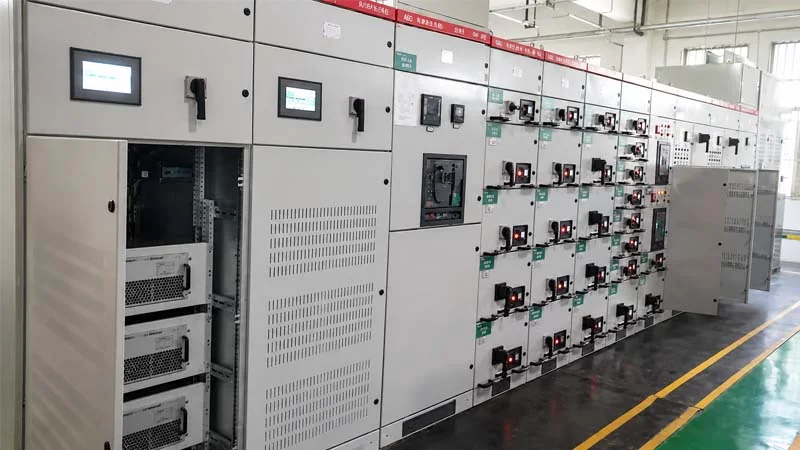
AHF modules installed alongside the main industrial distribution equipment.
Operating measurements collected at the defined electrical point during commissioning verification.
09. Recommended Solution
Winzele Active Harmonic Filters provide dynamic harmonic current compensation for industrial power systems. The configuration should be selected according to measured harmonic current, load variation and the required mitigation target.
Factory Quality Control
Each project configuration should be checked against its approved specification before shipment.
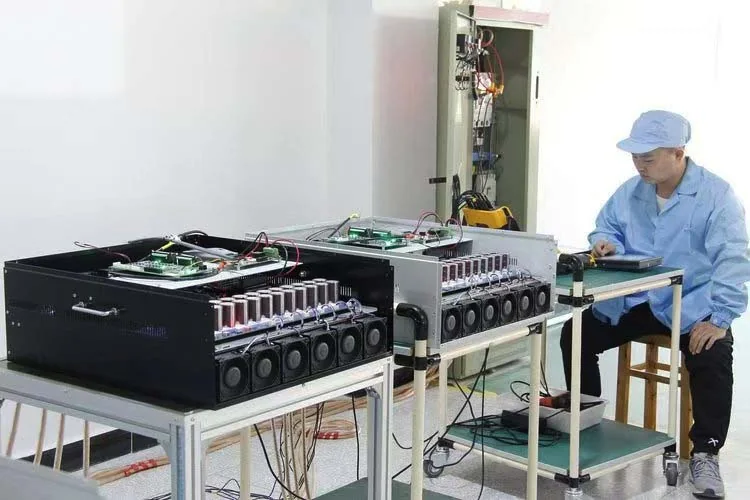
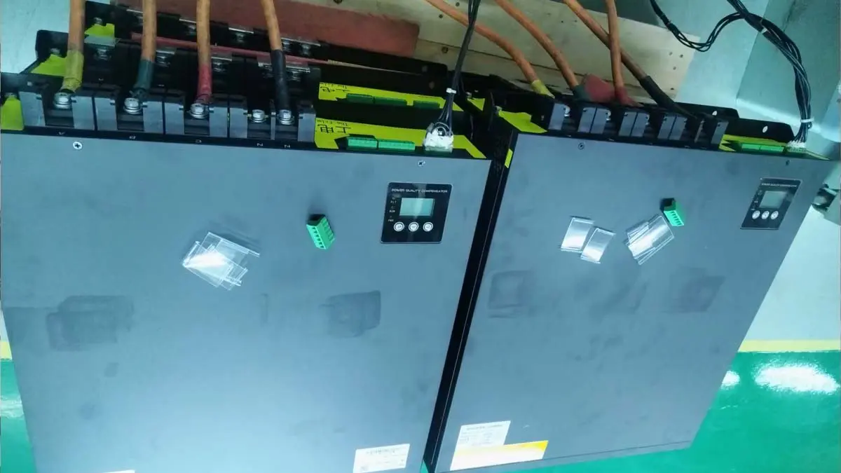
AHF power modules and cabinet assembly checked before final enclosure and inspection.
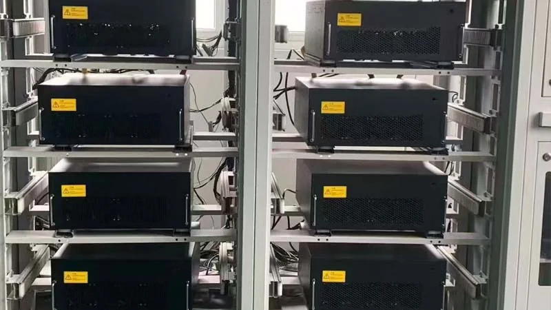
AHF modules connected for functional inspection against the approved project specification before delivery.
10. AHF Capacity Selection Checklist
AHF capacity is selected primarily by the harmonic current to be compensated—not only by transformer kVA or total load current. Reliable selection also considers the measured spectrum, load variation, mitigation target and engineering margin.
If measurement data is not available, send a single-line diagram, load list, equipment nameplates and operating information so our engineers can define the next assessment step.
11. Results and Project References
The examples below reference published Winzele application articles. Actual results depend on system conditions, load profile, measurement point and solution configuration.
Quantity: Current harmonic spectrum
Measurement point: Not identified in the published source
Load condition: Electric arc furnace operating
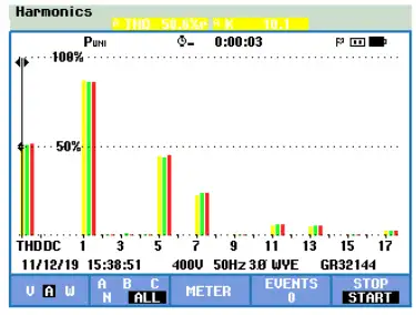
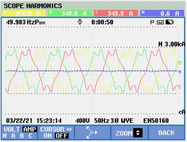
Reported condition: THDi fluctuating between 15% and 35%
Source: A Brief Introduction to the Applications of AHF
Project example: before AHF compensation
Quantity: Current harmonic spectrum
Measurement point: Not identified in the published source
Load condition: Electric arc furnace operating with AHF dynamic compensation
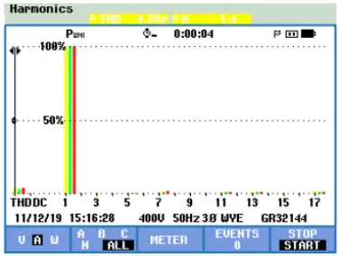
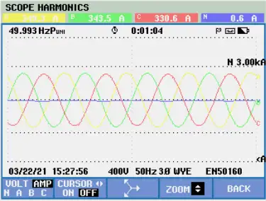
Reported result: THDi controlled within 8%
Source: A Brief Introduction to the Applications of AHF
Project example: after AHF compensationThe published AHF Active Harmonic Filter Application Case Compilation reports individual examples including THDi changing from 28% to below 5%, and another example with THDv changing from 8.5% to below 2% while THDi changed from 35% to below 5%. These are case-specific results, not general performance guarantees.
FAQ
Concise engineering guidance on measurement, CT location, AHF capacity selection and compliance expectations before a project is quoted.
Harmonic current is usually generated by nonlinear loads such as VFDs, rectifiers, UPS systems, welding machines, arc furnaces and switching power supplies. These loads draw current in a non-sinusoidal way.
THDi describes current distortion, while THDv describes voltage distortion. Harmonic current flowing through system impedance can create voltage distortion, so both values and the measuring point matter.
Warning signs include transformer or cable overheating, capacitor bank failure, nuisance tripping, control interference, motor overheating and unexplained losses. Measurement is still required before selecting equipment.
Measurements are commonly taken at the PCC, main bus and critical nonlinear loads. The correct point depends on whether the target is utility compliance, bus power quality or local load mitigation.
A CT measures current in real time, the controller extracts harmonic components, and the IGBT converter injects compensating current with opposite phase through a parallel connection.
An AHF is normally connected in parallel with the bus or distribution panel. It is not installed in series with the main power circuit.
Grid-side CTs are often used for centralized compensation, while load-side CTs can be used for local source compensation. Direction, phase sequence and wiring must match the control method.
The required AHF current rating should be based primarily on the harmonic current to be compensated, load profile, dominant harmonic orders, mitigation target and an appropriate engineering margin. Transformer kVA alone is not enough.
Yes. Winzele AHF specifications list parallel capability up to 20 machines, with one control panel able to control up to 8 units. Parallel design should consider CT wiring and control coordination.
Winzele AHF specifications include harmonic compensation, reactive compensation and three-phase load unbalance compensation. The enabled mode should be selected according to site priorities and device capacity.
No unconditional guarantee should be made before assessment. IEEE 519 evaluation is related to the PCC, system conditions, load profile, background distortion and the final solution configuration.
Useful information includes single-line diagram, load list, transformer capacity and impedance, system voltage, wire system, THDi, THDv, harmonic spectrum, CT position and installation environment.

Requirements Form
Provide the available electrical data. If you do not have measurement data, send your single-line diagram, load list, equipment nameplates and operating information.
Complete the essential project information first. Measurement fields are optional and can be left blank when data is not yet available.
Name, email and project message are collected by the existing inquiry form below.
Optional: enter measured values only when they are available.
The existing form does not support file uploads. Send the single-line diagram and measurement report by email after submitting the inquiry.
Share your system data and available measurement results with Winzele engineers. We will help define the assessment point, required AHF capacity, CT position and commissioning verification plan.
Request a Harmonic Assessment