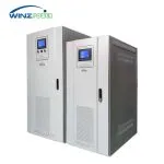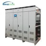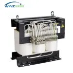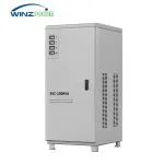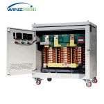

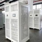
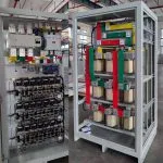
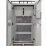
SCR Static Voltage Stabilizer
Static SCR voltage stabilizer designed for fast voltage correction and stable AC power.
Rated Power: 3–3000 kVA
Input Voltage: 220V / 380V / 400V / 415V / 440V / 480V(Customizable)
Input Range: ±15% / ±20% (Customizable)
Output Voltage: 220V / 380V / 400V / 415V / 440V / 480V(Customizable)
Frequency: 50/60 Hz ±10%
Voltage Accuracy: ±1% ~ ±5%
Response Time: 20 ms / 40 ms Configurable
Technology: SCR Semiconductor Switching
Product Introduction
The ZDBW/ZSBW series is a high-power static non-contact SCR voltage stabilizer designed for industrial AC power stabilization applications.
Based on power electronics, semiconductor switching and MCU digital control technology, this series provides fast voltage correction, high regulation accuracy and reliable operation for equipment requiring stable AC power supply.
Working principle
The ZDBW/ZSBW series adopts advanced power electronics and digital control technology.
Unlike servo motor voltage stabilizers that use mechanical adjustment components, SCR static voltage stabilizers regulate voltage through semiconductor switching technology without mechanical contact.
When voltage fluctuations are detected, the MCU controller controls the power semiconductor devices to adjust the compensation voltage amplitude and phase, maintaining a stable output voltage.
The SCR voltage stabilizer provides fast dynamic response (response time configurable at 20 ms or 40 ms), high precision voltage regulation, contactless operation, reduced mechanical maintenance requirements, strong interference resistance, long service life, high efficiency operation, automatic three-phase voltage balance and comprehensive protection functions.
SCR Voltage Compensation Principle
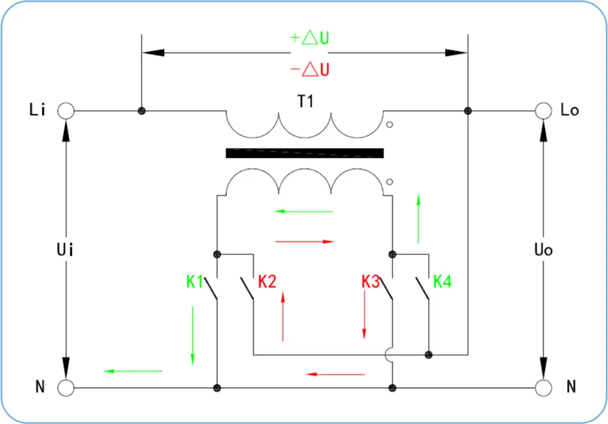 |
The SCR static voltage stabilizer regulates the output voltage by controlling the compensation voltage generated by the compensation transformer T1. When the input voltage drops, the SCR switching circuit controls the compensation transformer to add a positive compensation voltage to the supply voltage: Uo = Ui + ΔU When the input voltage rises, the switching circuit reverses the compensation polarity and subtracts the compensation voltage from the supply voltage: Uo = Ui – ΔU By controlling semiconductor switching states, the system rapidly adjusts the compensation voltage amplitude and polarity, maintaining stable output voltage with millisecond-level response. |
Digital Control System of SCR Voltage Stabilizer
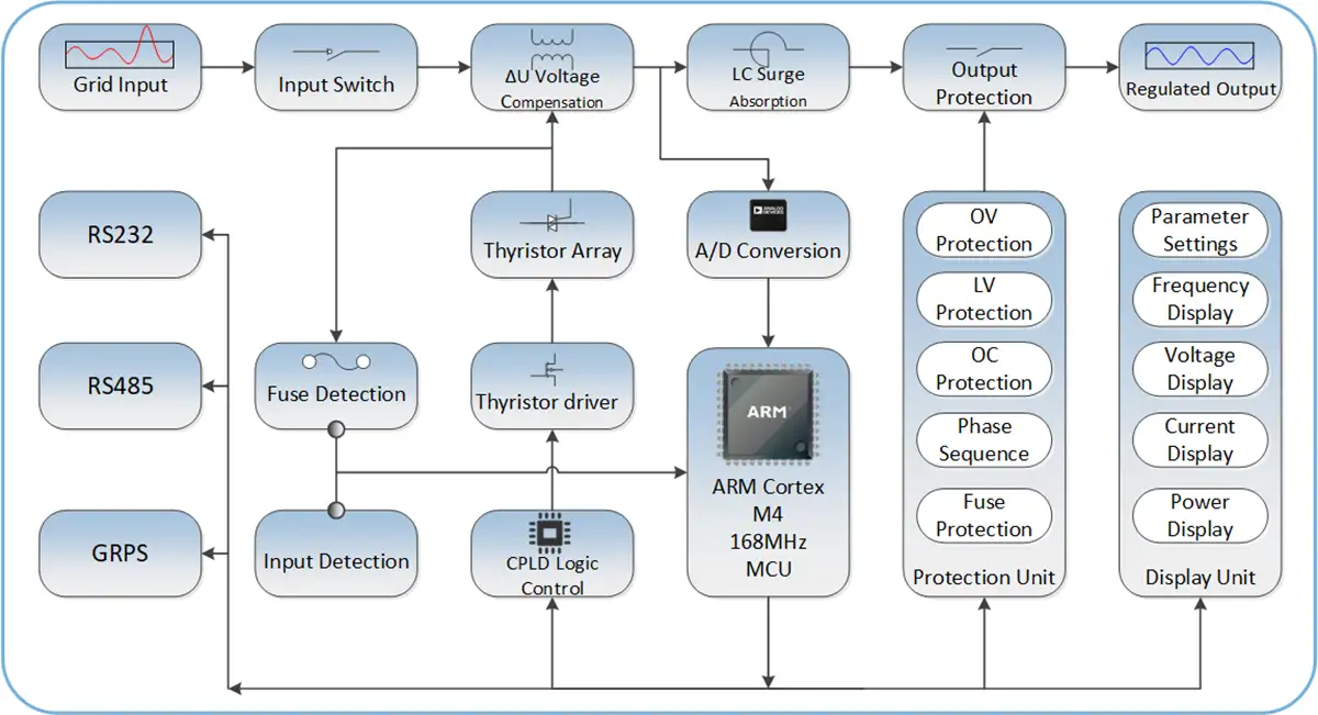
The SCR voltage stabilizer uses MCU-based digital control to monitor voltage variations, control thyristor switching states and adjust compensation voltage in real time.
SCR Voltage Stabilizer Topology Diagram
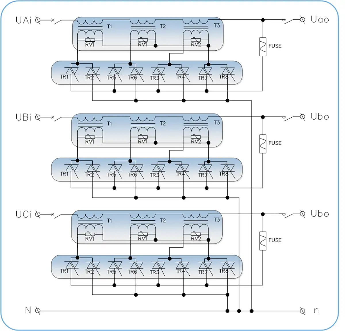
The three-phase topology uses independent compensation circuits and thyristor switching units for accurate voltage regulation.
Featured SCR Static Voltage Stabilizer Applications
These application cases show how Winzele SCR static voltage stabilizers are used for precision electronics manufacturing, machine tools, medical imaging equipment, and mobile field systems requiring stable AC voltage and fast voltage correction.
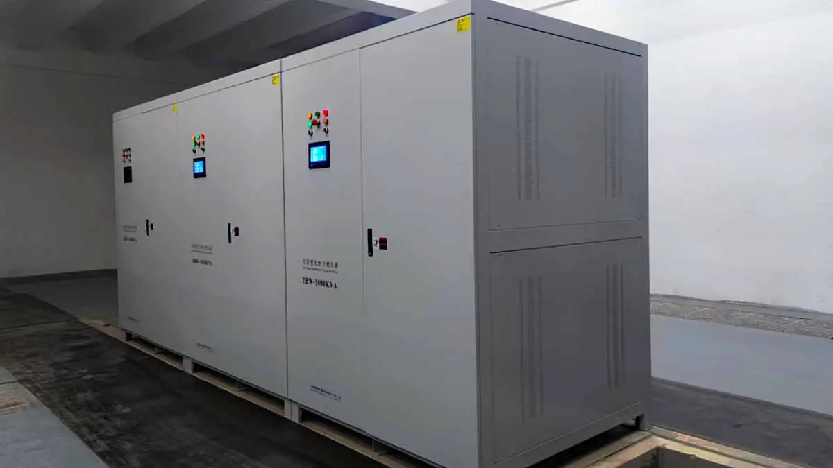
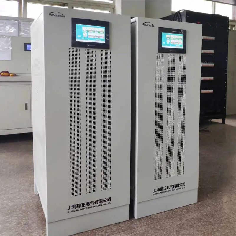
2×1000kVA SCR Voltage Stabilizers for Electronics Manufacturing
Two independent 1000kVA SCR static voltage stabilizers were installed for sensitive precision electronics manufacturing loads at LUXSHARE.
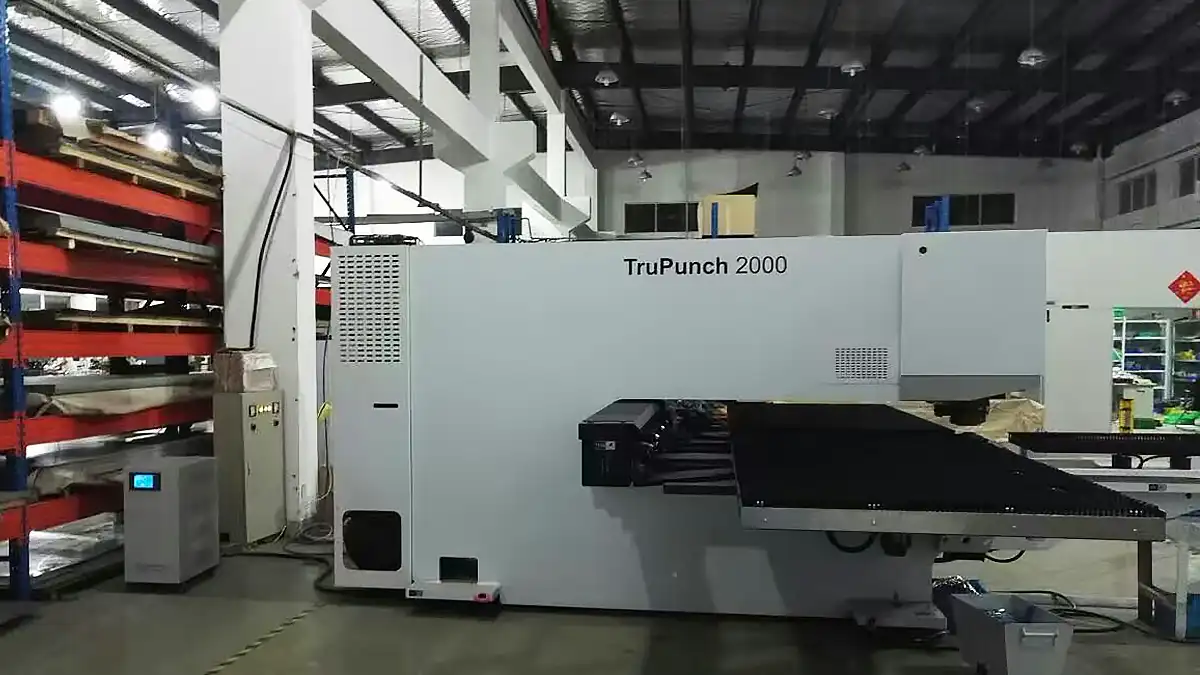
50kVA SCR Voltage Stabilizer for TRUMPF TruPunch 2000
A 50kVA SCR static voltage stabilizer supplies a TRUMPF TruPunch 2000 in a precision sheet metal processing workshop in Shanghai.
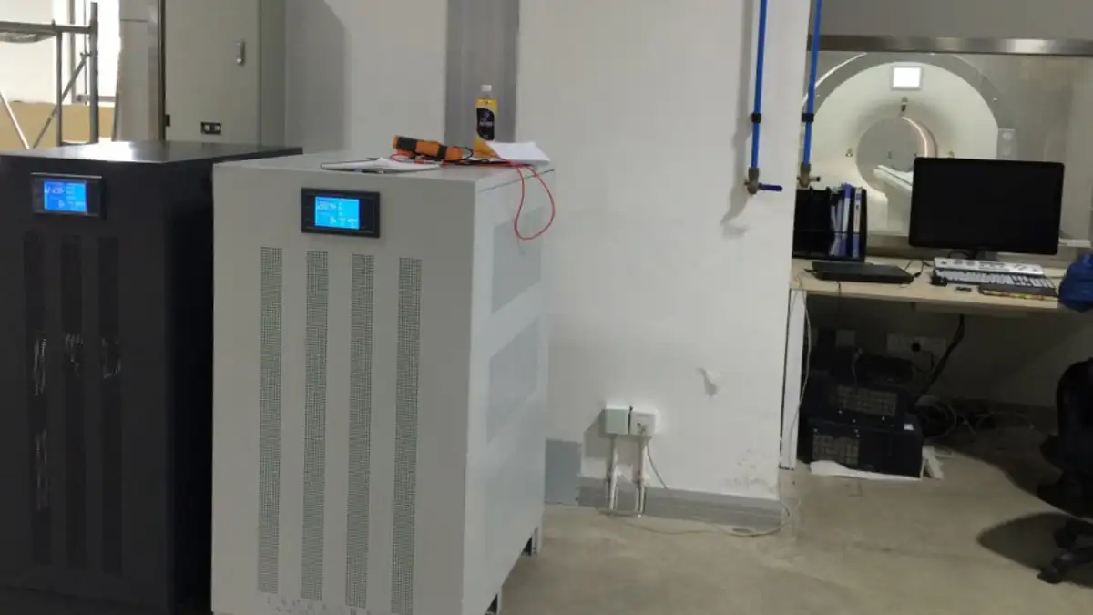
120kVA SCR Voltage Stabilizer for CT and DR Medical Imaging
A 120kVA SCR static voltage stabilizer provides stable AC power for sensitive CT and DR medical imaging equipment.
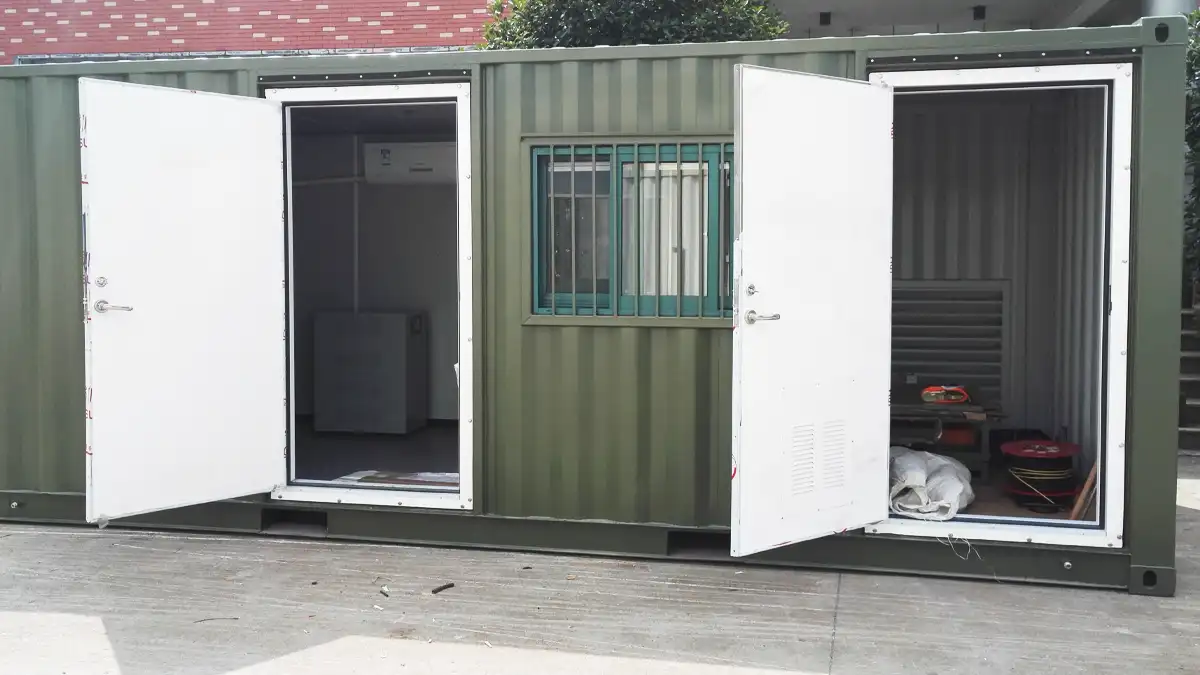
SCR Voltage Stabilizer for Mobile Satellite Communication Equipment
A static non-contact voltage stabilizer supports sensitive satellite communication and detection equipment powered by temporary AC supply or an onboard generator.
List Of ZSBW Static AVR Technical Parameters
Input Technical Parameters
| Item | Technical Indicators | Remark |
| Rated Voltage(Vac) | Three Phase 200V 208V 220V 380V 400V 440V 480V(Any voltage can be customized)Single phase 110V 220V 230V 380V(Any voltage can be customized) | Three phase three wire (L1, L2, L3) Ground(PE).Single phase two line (L, N) Ground(PE).The system can use a Neutral line or not.Any line entry method can be customized |
| Input Voltage Range(%) | (Rated Voltage)±20%.e.g.380V±20%(Customizable other voltage input ranges) | Generally, the input voltage range can be ±15% 20% 30% 40% of the rated voltage. |
| Input Frequency(Hz) | Default 50/60Hz ±10% | Other frequencies can be customized |
| Efficiency | 98% | |
| Output isolation transformer | △/Y or Y/Y | Optional |
Output Technical Parameters
| Item | Technical Indicators | Remark |
| Voltage Regulation Mode | Thyristor adjustment transformer | |
| Output voltage(Vac) | Three-phase 380V/400V (±10% adjustable) Single-phase 220V/230V (±10% adjustable) |
Other voltages can also be customized, e.g: Three-phase 200V 220 440V 480V or other. |
| Output voltage stability (average accuracy) | ±1-5% (2-5% for normal products) | |
| Dynamic Response time | 20/40ms(configurable) | |
| Output THD Increase | <0.1%(static and dynamic) | No additional waveform distortion (static and dynamic) is generated. The voltage THD increment is less than 0.1% |
| Output Frequency | Same as input frequency | |
| Three-phase imbalance | Three-phase voltage automatic control balance | |
| Applicable load type | Any load type (resistive, inductive, capacitive) | |
| Overload capacity | 120% 10min 140% 1min | |
| Bypass function | Automatic bypass when an internal fault occurs | Manual bypass optional |
Controller parameters
| Item | Technical Indicators | Remark |
| Control Mode | Full digital control | The analog part is used for input and output signal conditioning |
| Main control unit | The main chip uses STM32F4XX for control and measurement | Some models use ARM master control with DSP function |
| Control strategy | 8421 encoding | |
| SCR Drive Mode | Pulse transformer zero-crossing trigger | |
| Voltage Compensation time | 100ms | Load power 0-100% |
| Voltage and current measurement methods | True RMS sampling (three-phase synchronization) | RMS & FFT sampling 256 points |
| Voltage & Current Control Strategy | PID double closed loop control | |
| Communication interface | RS485/232/MODBUS-RTU Protocol | Optional TCP/IP, GPRS and other interfaces |
Display parameters
| Item | Technical Indicators | Remark |
| Display Media | Industrial touch screen(7″or 10″) | Other sizes of LCD can also be customized |
| Display electrical parameters |
Input three-phase voltage and frequency; Output three-phase line voltage and frequency; Output line voltage average value; Output power factor;Output three-phase current; Output active power and apparent power; |
|
| Display alarm information | Input overvoltage (OV), overcurrent (OC); input undervoltage (UV); Fuse failure; Overload;Phase sequence fault; and other fault information | |
| Display accuracy | The accuracy is Class 0.5s | |
| Voltage display resolution | 0.1V | |
| Current display resolution | 0.1A |
Protection
| Item | Technical Indicators | Remark |
| Protection List | Input overvoltage (OV), overcurrent (OC); input undervoltage (UV); SCR module failure; heat sink overheat; transformer overheat; and Short Circuit. | |
| Protection Action | Cut off output and alarm;Automatic bypass;Automatically start after failure recovery | Fault dry contacts can be configured(NC&NO) |
The Environment
| Item | Technical Indicators | Remark |
| Working Temperature(℃) | -35℃+55℃ | Extreme temperature environments require special customization or derating |
| Relative Humidity(RH) | 10%-90%(20℃±5℃) | |
| Altitude | <2000m | For every 1000m increase in altitude, the rating should be derated by 10%. |
| IP Class | IP20 | Other IP Classes such as outdoor IP33 can be customized |
| Other special requirements can be communicated with winzele | ||
List of ZSBW Static AVR Models & Products
1.Three-phase Model List
Small Capacity (20-50 kVA)
| Type |
Capacity (kVA) |
Current (A) |
Dimension W×D×H(mm) |
| ZSBW-20KVA | 20 | 30 | 350*600*750(Locking Castor Wheel) |
| ZSBW-30KVA | 30 | 45.6 | |
| ZSBW-50KVA | 50 | 76 | 390*650*870mm(Locking Castor Wheel) |
Medium Capacity (80-250 kVA)
| Type |
Capacity (kVA) |
Current (A) |
Dimension W×D×H(mm) |
| ZSBW-80KVA | 80 | 121.6 | 460*700*1200mm |
| ZSBW-100KVA | 100 | 152 | |
| ZSBW-120KVA | 120 | 182 | |
| ZSBW-150KVA | 150 | 228 | 760*660*1600mm |
| ZSBW-180KVA | 180 | 274 | |
| ZSBW-200KVA | 200 | 304 | |
| ZSBW-250KVA | 250 | 380 |
Large Capacity (300-600 kVA)
| Type |
Capacity (kVA) |
Current (A) |
Dimension W×D×H(mm) |
| ZSBW-300KVA | 300 | 456 | 1150*850*2000mm |
| ZSBW-350KVA | 350 | 532 | |
| ZSBW-400KVA | 400 | 608 | |
| ZSBW-500KVA | 500 | 760 | 1200*950*2200mm |
| ZSBW-600KVA | 600 | 912 |
Extra-Large Capacity (800-3000 kVA)
| Type |
Capacity (kVA) |
Current (A) |
Dimension W×D×H(mm) |
| ZSBW-800KVA | 800 | 1216 | 1500*1000*2200mm |
| ZSBW-1000KVA | 1000 | 1520 | |
| ZSBW-1200KVA | 1200 | 1824 | |
| ZSBW-1500KVA | 1500 | 2280 | 1600*1000*2200mm |
| ZSBW-2000KVA | 2000 | 3040 | 2000*1100*2200mm |
| ZSBW-2500KVA | 2500 | 3800 | |
| ZSBW-3000KVA | 3000 | 4560 | 2400*1200*2200mm |
2.Single-phase Model List
Small Capacity (3-30 kVA)
| Type |
Capacity (kVA) |
Current (A) |
Dimension W×D×H(mm) |
| ZDBW-3KVA | 3 | 13.6 | 220*500*370mm |
| ZDBW-5KVA | 5 | 22.7 | 260*600*400mm |
| ZDBW-10KVA | 10 | 45.5 | 350*600*400mm |
| ZDBW-15KVA | 15 | 68 | |
| ZDBW-20KVA | 20 | 91 | 390*650*670mm |
| ZDBW-30KVA | 30 | 136 |
Large Capacity (50-100 kVA)
| Type |
Capacity (kVA) |
Current (A) |
Dimension W×D×H(mm) |
| ZDBW-50KVA | 50 | 227 | 390*650*870mm |
| ZDBW-60KVA | 60 | 272 | |
| ZDBW-80KVA | 80 | 363 | 460*700*1200mm |
| ZDBW-100KVA | 100 | 456 |
Recommended Applications
SCR static voltage stabilizers are suitable for equipment that requires stable AC voltage and fast correction during rapid voltage fluctuations or sudden voltage changes.
- Precision electronics and automated manufacturing equipment
- Medical imaging equipment such as CT and DR systems
- Precision machine tools and sheet metal processing equipment
- Testing, laboratory and environmental simulation equipment
- Communication and satellite-related electronic systems
- Other voltage-sensitive industrial loads requiring fast, contactless regulation
Manufacturing Process and Quality Control
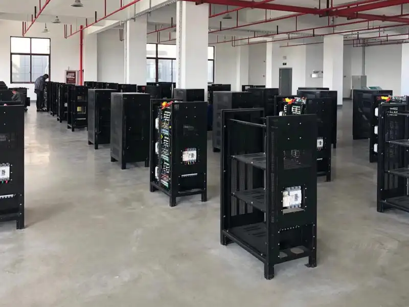
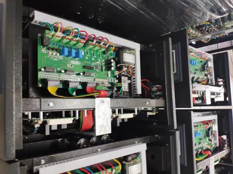
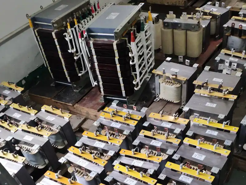
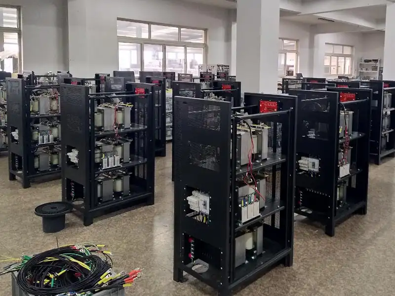
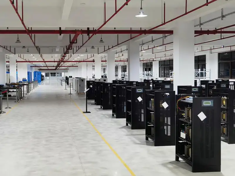
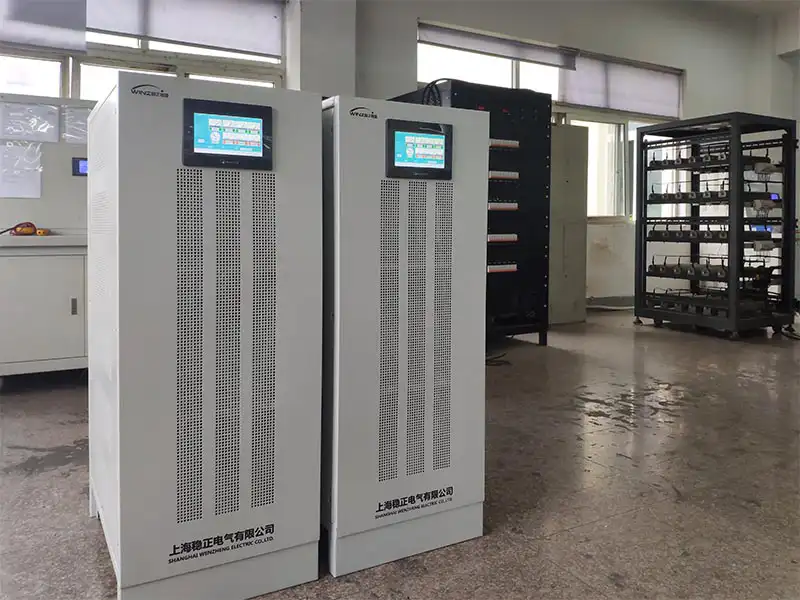
As a manufacturer of SCR static voltage stabilizers, Winzele controls the complete production process, including power electronics assembly, compensation transformer integration, system assembly, and final performance testing. The following photos show key manufacturing and quality inspection stages of SCR voltage stabilizer production.
FAQ
What is the difference between an SCR static voltage stabilizer and a servo motor voltage stabilizer?
SCR static voltage stabilizers use semiconductor switching technology for contactless voltage regulation and fast response. Servo motor voltage stabilizers use a servo motor and mechanical voltage adjustment structure. The two types are designed for different operating requirements rather than as direct replacements for each other.
How fast does an SCR static voltage stabilizer respond to voltage fluctuations?
The dynamic response time can be configured at 20 ms or 40 ms according to application requirements and system settings. Faster response is typically selected for loads that are more sensitive to rapid voltage changes.
What types of equipment are suitable for SCR static voltage stabilizers?
SCR static voltage stabilizers are commonly used with precision electronics, medical imaging equipment, machine tools, testing equipment, communication systems and other loads that require stable AC voltage and fast voltage correction.
Can SCR static voltage stabilizers be used for large-capacity industrial applications?
Yes. The ZSBW series covers a wide capacity range, including large three-phase industrial systems. Capacity, input voltage range and output voltage can be selected according to the actual load and power supply conditions.
Does an SCR static voltage stabilizer require mechanical maintenance?
The SCR regulation process does not rely on servo motor movement or carbon-brush adjustment. This reduces mechanical wear and related maintenance requirements. Routine inspection of electrical connections, cooling, protection devices and other system components is still recommended.
Can the voltage range, protection and communication functions be customized?
Yes. Input and output voltage, voltage regulation range, protection settings, bypass functions and communication interfaces such as RS485 / MODBUS-RTU can be configured according to project requirements.
Get a Quick Quote
Contact our sales team for pricing, technical specifications, and delivery information.