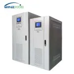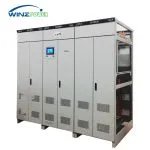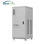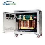

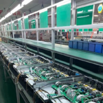
Static Var Generator (SVG)
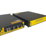
Modular Static Var Generator for Fast and Continuous Reactive Power Compensation
Rated Capacity: 30 / 50 / 75 / 100 kVAr
Cabinet Capacity: Up to 600 kVAr
System: 400 V, 3-Phase 4-Wire
Compensation: Inductive & Capacitive
Response Time: <20 ms
Structure: Modular Design
Provides fast, stepless compensation of inductive and capacitive reactive power to improve power factor under rapidly changing load conditions.
Product Introduction
Winzele WZ-SVG is a shunt-connected Static Var Generator designed for dynamic reactive power compensation and power-factor correction in industrial low-voltage systems.
WZ-SVG provides continuous, stepless adjustment of inductive and capacitive reactive power, helping the upstream electrical system maintain the configured power-factor target as load conditions change. It is particularly suitable for rapidly varying loads, fluctuating power factor, and systems that may alternate between lagging and leading operating conditions.
Dynamic Reactive Power Compensation
WZ-SVG is connected in parallel with the distribution system at the point of common coupling (PCC). Current transformers measure the relevant load or system current, and the controller continuously determines the reactive-current component required to reach the configured power-factor target. The power converter then regulates the compensating current through the coupling reactor.
For an inductive load, current lags voltage. The SVG supplies a capacitive reactive-current component locally, reducing the lagging reactive current that must be supplied through the upstream transformer and feeder.
For a capacitive or overcompensated system, current leads voltage. The SVG operates in the opposite direction and absorbs the corresponding capacitive reactive component, moving the upstream current back toward the configured power-factor target.
The SVG does not change the active-power requirement of the load. Its primary function is to control reactive-current exchange and the phase relationship between upstream voltage and current, while drawing only the active power required for converter losses and DC-link regulation.
How a Static Var Generator Works
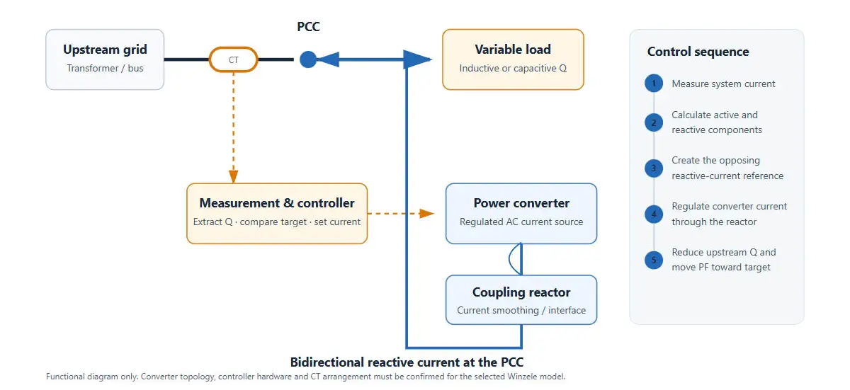
The functional sequence is:
- The CT measures the selected system or load current.
- The controller separates active and reactive current components.
- The controller creates an opposing reactive-current reference.
- The converter regulates its AC current through the coupling reactor.
- At the PCC, the SVG current combines with the load current, reducing the upstream reactive component and moving power factor toward the configured target.
Resistive, Inductive and Capacitive Loads
At the fundamental frequency, the phase relationship between voltage and current identifies displacement reactive power:
- Resistive: current is in phase with voltage; φ ≈ 0°.
- Inductive: current lags voltage; motors, transformers, reactors and induction equipment commonly create this condition.
- Capacitive: current leads voltage; an oversized capacitor bank, a lightly loaded cable system or some filters can create this condition.
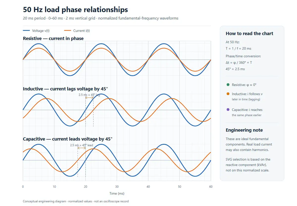
At 50 Hz, one cycle is 20 ms. A 45° phase shift therefore equals 2.5 ms:
Δt = (φ / 360°) × T
The chart uses ideal, normalized fundamental components. Real industrial current can also contain harmonic distortion. Phase displacement and harmonics must be measured and evaluated separately.
What Changes After SVG Compensation
For the illustrative inductive case below, load current lags voltage by 45°. The load current can be separated into an active component aligned with the voltage and a reactive component in quadrature. The SVG supplies the opposite reactive component locally.
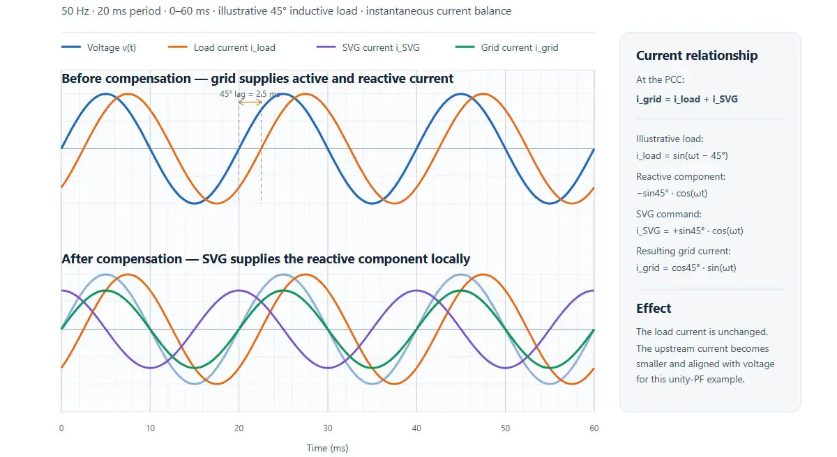
At the PCC:
i_grid(t) = i_load(t) + i_SVG(t)
For the normalized unity-power-factor illustration:
i_load = sin(ωt − 45°)
i_SVG = sin45° × cos(ωt)
i_grid = cos45° × sin(ωt)
The load current remains present. The SVG supplies its reactive component locally, so the upstream grid current becomes smaller and moves into phase with voltage in this example. A real installation can use a non-unity target and may retain residual Q because of rating limits, control settings, CT error, load transients or system conditions.
Dynamic Tracking of Reactive Load Changes
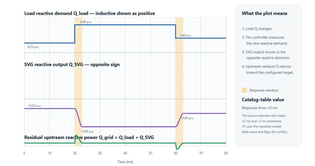
WZ-SVG provides a full response time of <20 ms, enabling continuous reactive-power adjustment for rapidly changing loads.
Reactive Power and Apparent Power After Compensation
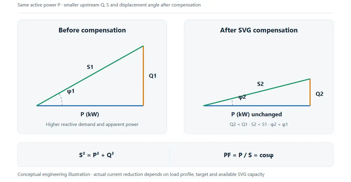
Before compensation, the upstream system carries active power P and the larger reactive component Q1, producing apparent power S1 and angle φ1. After SVG compensation, P is substantially unchanged, while upstream reactive power decreases from Q1 to Q2. Apparent power decreases from S1 to S2, and the displacement angle becomes smaller.
S² = P² + Q² PF = P / S = cosφ
The diagram is conceptual. Actual current reduction and any tariff effect depend on the measured operating profile, selected SVG capacity and local billing rules.
Why Use an SVG Instead of Only a Capacitor Bank?
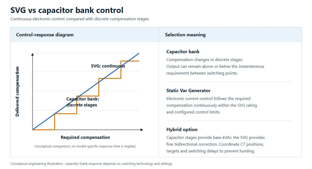
A correctly engineered capacitor bank remains economical for stable inductive loads. An SVG becomes particularly useful when reactive demand changes quickly, when both lagging and leading conditions occur, or when discrete steps cannot hold the desired target closely.
| Comparison | Capacitor bank / APFC | Static Var Generator |
|---|---|---|
| Compensation method | Discrete capacitor steps | Continuous electronic current control |
| Reactive direction | Primarily capacitive output; leading-PF correction requires a different arrangement | Continuous capacitive-to-inductive adjustment within rating |
| Step resolution | Limited by installed stage sizes | Stepless within the converter’s current and control limits |
| Dynamic loads | Limited by switching method, delay and permitted operating rate | Designed to track changing Q electronically |
| Over/under-compensation | Can occur between stages | Regulates toward the configured target |
| Primary maintenance focus | Capacitors, fuses, contactors/thyristors and reactors | Fans, sensors, converter modules, DC link, connections and firmware |
| Selection basis | Required kVAr, stage plan, detuning and duty | Required dynamic kVAr, voltage, wiring, CT arrangement and environment |
Typical Problems Addressed
Low or Fluctuating Power Factor
Motors, transformers and cyclic industrial processes can impose varying lagging reactive demand. The SVG supplies compensating current up to its available rating and moves upstream power factor toward the configured target.
Leading Power Factor
Fixed capacitor stages can leave a lightly loaded system overcompensated. An SVG can operate in the inductive direction to absorb the corresponding capacitive reactive component, subject to the selected model rating.
Rapidly Changing Loads
Welders, cranes, hoists, rolling equipment and intermittent production machines can change Q faster than conventional staged compensation follows. Electronic regulation avoids dependence on coarse step size.
Capacity and Voltage-Drop Constraints
Reducing upstream reactive current can reduce apparent current for the same real-power demand. This may reduce feeder or transformer loading and voltage drop when reactive current is the limiting contributor. Any capacity release or energy-cost result requires a site study and is not guaranteed by the product alone.
Complete WZ-SVG Technical Data
Model-Code Definition
| Code element | Meaning |
|---|---|
| WZ | Company code: Shanghai Winzele Electric Co., Ltd. |
| SVG | Static Var Generator |
| 4L | Three-phase four-wire system |
| 400V | 400 V product class |
| XXK | Rated reactive capacity in kVAr: 30K, 50K, 75K or 100K |
| M | Modular construction |
Model template: WZ-SVG/4L-400V-XXK/M
WZ-SVG Module Models and Dimensions
| Winzele model | Rated capacity | Calculated current at 400 V* | Module dimensions W×H×D | Structure |
|---|---|---|---|---|
| WZ-SVG/4L-400V-30K/M | 30 kVAr | 43.3 A | 480×200×560 mm | Module |
| WZ-SVG/4L-400V-50K/M | 50 kVAr | 72.2 A | 480×200×560 mm | Module |
| WZ-SVG/4L-400V-75K/M | 75 kVAr | 108.3 A | 680×200×560 mm | Module |
| WZ-SVG/4L-400V-100K/M | 100 kVAr | 144.3 A | 680×200×560 mm | Module |
* Calculated current uses I = Q / (√3 × 400 V).
Single-Cabinet Capacity and Dimensions
| Single-cabinet SVG capacity | Example modular build | Cabinet dimensions W×D×H |
|---|---|---|
| 100 kVAr | 2×50 kVAr or 1×100 kVAr | 600×600×2200 mm |
| 200 kVAr | 2×100 kVAr | 800×600×2200 mm |
| 300 kVAr | 3×100 kVAr | 600×800×2200 mm |
| 600 kVAr | 6×100 kVAr | 800×800×2200 mm |
Final cabinet configuration, module quantity, ventilation clearance, cable entry and shipping split are selected for the project installation.
Electrical and Control Specifications
| Electrical | |
|---|---|
| Product class | 400 V |
| Operating voltage | 380 VAC, −20% to +15% |
| Frequency | 50 Hz, −10% to +10% |
| Wiring | 3-phase 4-wire (4L) |
| Measurement | |
| CT ratio range | 100:5 to 10000:5 |
| CT location | Load side or grid side selectable |
| Capacity | |
| Module ratings | 30 / 50 / 75 / 100 kVAr |
| Single-cabinet ratings | 100 / 200 / 300 / 600 kVAr |
| Expansion | |
| Parallel modules | Up to 12 modules |
| Compensation | |
| Reactive-power range | Capacitive to inductive, continuously adjustable |
| Power-factor setting | −1 to +1 within rated capacity |
| Power-factor target | Up to 0.99 |
| Dynamic | |
| Full response time | <20 ms |
| Efficiency | |
| Active-power loss | <2.5% at full load |
| Cooling | |
| Method | Intelligent forced-air cooling with temperature-based fan control |
| Acoustic | |
| Noise | <60 dB |
| Communication | |
| Interface / protocol | RS485 / Modbus |
| Monitoring | |
| Local / central | Independent module monitoring or centralized monitoring |
| HMI | |
| Central display | Optional external 7-inch touch screen for up to 12 modules |
| Protection | |
| Functions | Overvoltage, undervoltage, overcurrent, overtemperature, short circuit and additional protections |
| Enclosure | |
| Protection class | IP20 |
| Environment | |
| Operating temperature | −10 to +45°C |
| Relative humidity | <95%, non-condensing |
| Altitude | <5000 m; 1% derating per additional 100 m above 1000 m |
| Installation | |
| Standard structure | Modular (/M) for the listed WZ-SVG models |
Secondary Power-Quality Functions
Optional secondary compensation is available for selected 2nd–13th harmonic currents. Harmonic use is limited to approximately 50% of rated current, with >97% filtering within equipment capacity. WZ-SVG remains primarily a reactive-power compensation product; Winzele AHF is the dedicated solution when harmonic-current mitigation is the main objective.
How to Size an SVG
From Active Power and Power Factor
For a three-phase load with active power P, initial displacement power factor PF1 and target PF2:
Q_required = P × [tan(arccos(PF1)) − tan(arccos(PF2))]
Example only:
- Active power: 500 kW
- Initial PF: 0.75 lagging
- Target PF: 0.98
- tan(arccos 0.75) ≈ 0.882
- tan(arccos 0.98) ≈ 0.203
- Q_required ≈ 500 × (0.882 − 0.203) = 339.5 kVAr
The engineering selection must then consider load variation, leading operation, voltage, frequency, wiring, duty cycle, CT location, ambient temperature, altitude, expansion margin and available model increments.
From Measured Reactive Power
For variable loads, use interval or high-speed measurements rather than one spot reading:
- Record positive and negative Q through representative production states.
- Identify the maximum inductive and maximum capacitive demand.
- Confirm how quickly Q changes and how long each condition lasts.
- Select the voltage family and wiring arrangement.
- Apply thermal and altitude derating.
- Confirm whether the SVG must coordinate with existing capacitor banks.
- Select capacity to cover the required operating envelope and margin.
Do not size an SVG only from transformer kVA, utility bills or a single power-factor value if the load is dynamic.
CT Position and System Integration
WZ-SVG is connected in parallel with the 0.4 kV distribution bus. In the arrangement shown below, the CT is installed on the load side of the SVG connection point so that the controller measures the current associated with the compensated downstream loads.
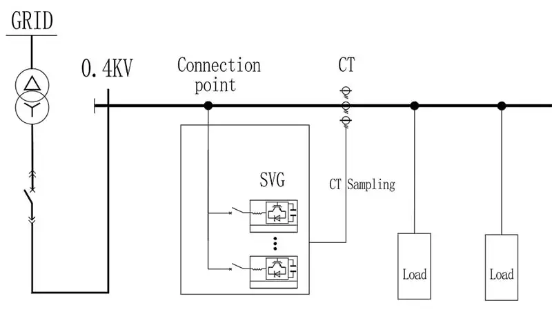
Correct CT installation is essential for stable compensation. The project design should confirm the CT ratio, secondary rating, polarity, installation direction, accuracy class, burden, cable length and controller configuration. Incorrect CT polarity or sampling position may cause incorrect compensation or prevent the controller from detecting the intended load current.
Where the SVG operates together with an existing capacitor bank or other reactive-power compensation equipment, the CT arrangement, power-factor target and control settings should be coordinated as part of the overall system design.
The SVG branch should include suitable isolation, overcurrent protection, protective earthing, conductor sizing and short-circuit coordination according to the project electrical design.
Mechanical Cabinet Layout
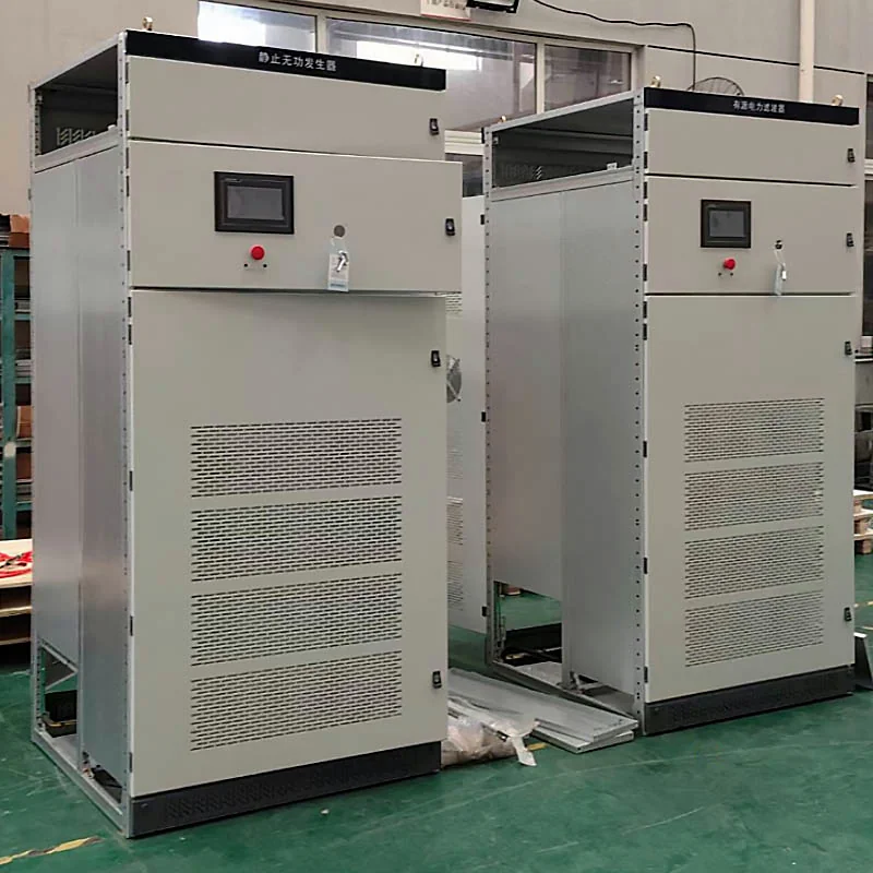
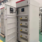
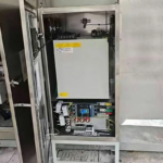
WZ-SVG systems can be configured as modular cabinet assemblies according to the required reactive-power capacity and project configuration.
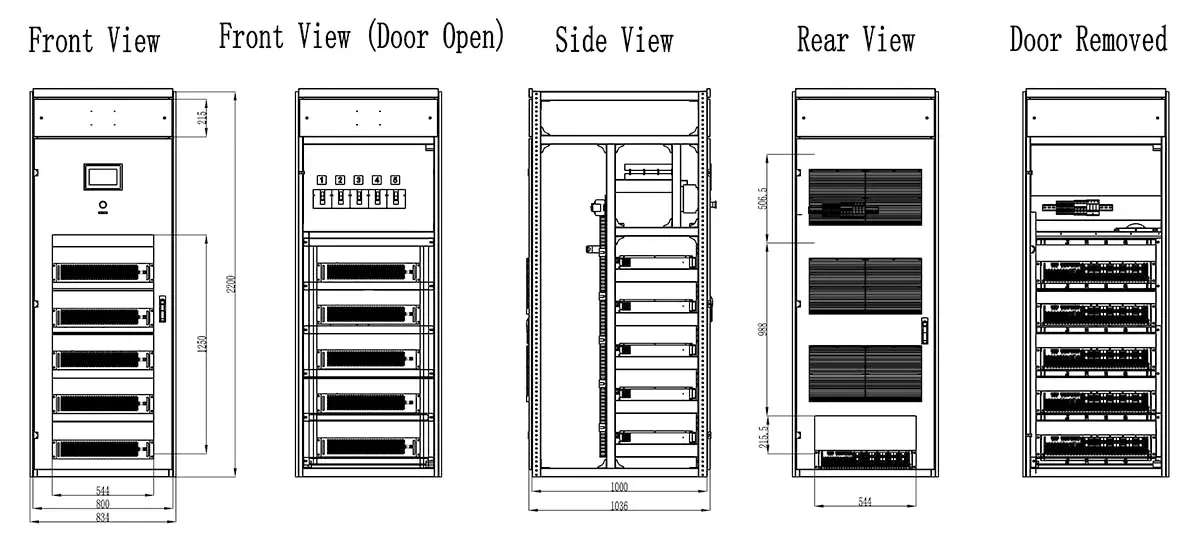
Multiple SVG power modules can be installed within one cabinet. The front and door-open views show the module stacking and control section, while the side and rear views show cabinet depth, internal arrangement and ventilation paths.
Cabinet dimensions, module quantity and internal arrangement vary with the selected kVAr capacity and project requirements. The drawing above therefore represents a typical cabinet configuration rather than a universal enclosure size for every WZ-SVG rating.
Recommended Applications
- motor, pump, fan and compressor systems with variable operating duty;
- cranes, hoists, elevators and material-handling systems;
- welding and rapidly cycling production equipment;
- rolling mills, presses and industrial process lines;
- installations that alternate between lagging and leading power factor;
- systems with existing capacitor banks that need fine dynamic correction;
- 400 V, three-phase four-wire industrial distribution using a WZ-SVG module or cabinet configuration.
An SVG is not a substitute for an AHF when harmonic-current distortion is the primary problem. It is also not a substitute for voltage regulation, UPS ride-through, motor-starting studies or fault-current mitigation.
SVG and AHF Have Different Control Objectives
| Topic | WZ-SVG | Winzele AHF |
|---|---|---|
| Primary problem | Dynamic reactive power and displacement power factor | Harmonic current |
| Main selection unit | kVAr | A |
| Product class | 400 V, 4L | 200 / 220 / 400 / 480 / 690 V |
| Module ratings | 30 / 50 / 75 / 100 kVAr | 30–150 A |
| Cabinet ratings | 100 / 200 / 300 / 600 kVAr | Model-dependent current rating |
| Full response time | <20 ms | ≤5 ms |
| Frequency | 50 Hz, −10% to +10% | 50/60 Hz ±10% |
| Communications | RS485 / Modbus | RS485 / CAN / Modbus |
| Protection class | IP20 | IP20 |
| Temperature | −10 to +45°C | −25 to +55°C |
| Mechanical form | /M modules and configured cabinets | Rack / wall / cabinet |
| Harmonic function | Optional secondary 2nd–13th function | Primary harmonic-current control |
The values are product-specific: select WZ-SVG capacity in kVAr and Winzele AHF capacity in amperes.
Frequently Asked Questions
What is a Static Var Generator?
An SVG is a shunt-connected power-electronic system that dynamically provides or absorbs reactive current. Its main purpose is reactive-power compensation and power-factor regulation.
What WZ-SVG module ratings are available?
The WZ-SVG family includes 30, 50, 75 and 100 kVAr modules using the format WZ-SVG/4L-400V-XXK/M.
What single-cabinet ratings are available?
Single-cabinet ratings are 100, 200, 300 and 600 kVAr. Module quantity, cabinet layout and thermal design are configured for each project.
Can one SVG compensate both inductive and capacitive loads?
Yes. WZ-SVG provides continuous adjustment from capacitive to inductive reactive output within the rated capacity.
Does an SVG remove harmonics?
Optional 2nd–13th harmonic-current compensation is available within the specified capacity limit. WZ-SVG remains primarily a reactive-power product; use Winzele AHF when harmonic-current mitigation is the main objective.
How fast is the WZ-SVG?
The WZ-SVG full response time is <20 ms.
What power system is covered?
This family is designed for the 400 V class and three-phase four-wire (4L) systems, with an operating-voltage range of 380 VAC, −20% to +15%.
Can an SVG work with an existing capacitor bank?
Yes, a coordinated hybrid arrangement can be engineered. CT positions, ratios, target settings, stage delays and control priorities must be designed together to prevent hunting or overcompensation.
Does SVG compensation always reduce electricity cost?
Not necessarily. It can reduce reactive demand and apparent current, but financial results depend on utility tariffs, demand intervals, operating profile and whether power factor is currently penalized.
What information is required for selection?
Provide the single-line diagram, voltage, frequency, wiring, measured kW/kVAr/PF trend, maximum leading and lagging Q, load-change timing, CT information, existing capacitor banks or filters, ambient temperature, altitude and installation constraints.
Factory & Quality Management
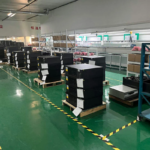
Winzele applies a structured production and verification flow from module assembly through controlled aging and shipment preparation.
|
1. Batch Production of SVG 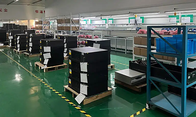 |
2. SVG Aging Test Bench 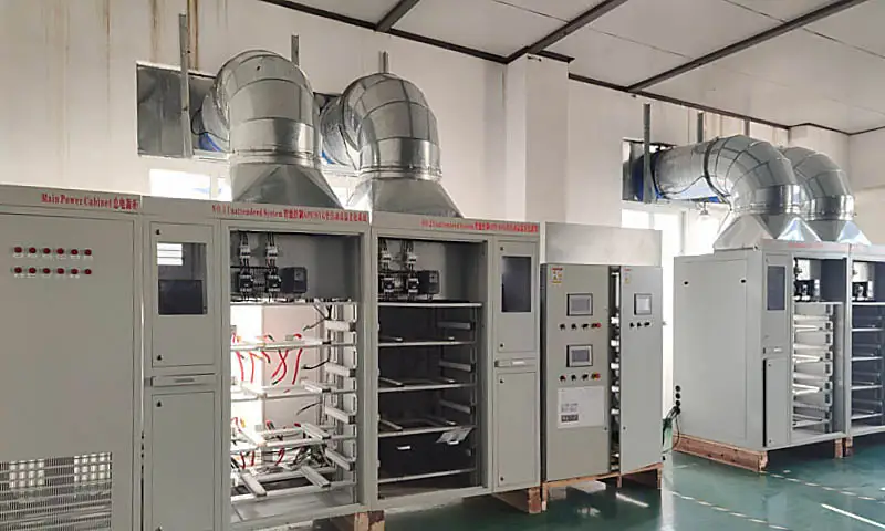 |
|
3. Batch SVG Aging 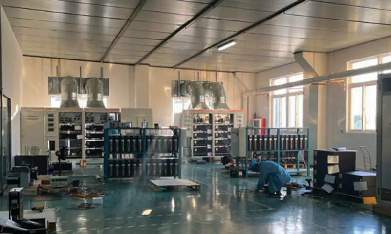 |
4. SVG Shipment  |
Project-specific inspection records, test scope, acceptance criteria, packing method and shipping marks should be confirmed with the order documentation.
Request an SVG Selection
Send Winzele the following:
- system voltage, frequency and 3P3W/3P4W arrangement;
- one-line diagram and proposed connection point;
- recorded kW, kVAr and PF trends through representative duty cycles;
- maximum inductive and capacitive reactive demand;
- CT ratio, secondary rating, location and orientation;
- existing APFC, filters, reactors or generators;
- ambient temperature, altitude, enclosure and cable-entry requirements;
- desired power-factor target and applicable utility requirements.
Get a Quick Quote
Contact our sales team for pricing, technical specifications, and delivery information.