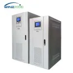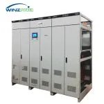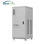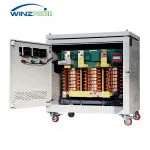
1500kW 380V to 200V Transformer System for Semiconductor Manufacturing Equipment


Industrial dry type isolation transformers designed for voltage conversion, electrical isolation, and reliable power supply interfaces for sensitive equipment and industrial systems.
Rated Power: 3~2500kVA
Voltage Range: Up to 1140V, Customizable
Phase: Three Phase
Frequency: 50/60Hz (Special frequency up to 1000Hz)
Insulation Class: F/H/B
Application: Industrial Equipment & Power Systems
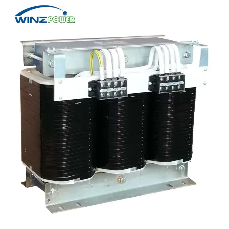
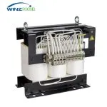
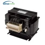
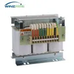
Three phase dry type isolation transformers are designed for voltage conversion, electrical isolation and reliable power interfaces in industrial applications. The primary and secondary windings are electrically separated, so the equipment side operates on an independent circuit instead of being directly connected to the supply line. The dry type construction uses air as the cooling and insulating medium and adopts an oil-free design, which simplifies indoor installation close to the equipment it serves. Industrial isolation transformers of this type are commonly used where machinery requires a different voltage level from the local supply, or where an isolated power interface is needed for stable operation.
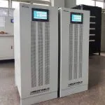
Typical applications include semiconductor equipment, CNC machine tools, medical equipment and industrial automation systems, as well as imported equipment that requires voltage compatibility with local supply standards. The transformer is also commonly installed in front of UPS units to provide an isolated input interface. For real installations, the Winzele project cases in the section below include semiconductor manufacturing equipment powered through three phase dry type isolation transformers.
The transformer converts AC voltage levels between the primary and secondary sides while keeping the two windings electrically isolated. It is suitable for equipment that requires an independent power interface.
The windings are vacuum impregnated as a whole and use insulation class F or H. The dry type construction is suitable for indoor industrial installation.
Input voltage, output voltage, frequency, connection group, winding configuration and grounding requirements can be engineered to match the application.
Optional electrostatic shielding and neutral grounding configurations are available. When properly designed and grounded, these configurations reduce common-mode disturbances.
Understanding transformer electrical isolation, winding structure and mechanical design.
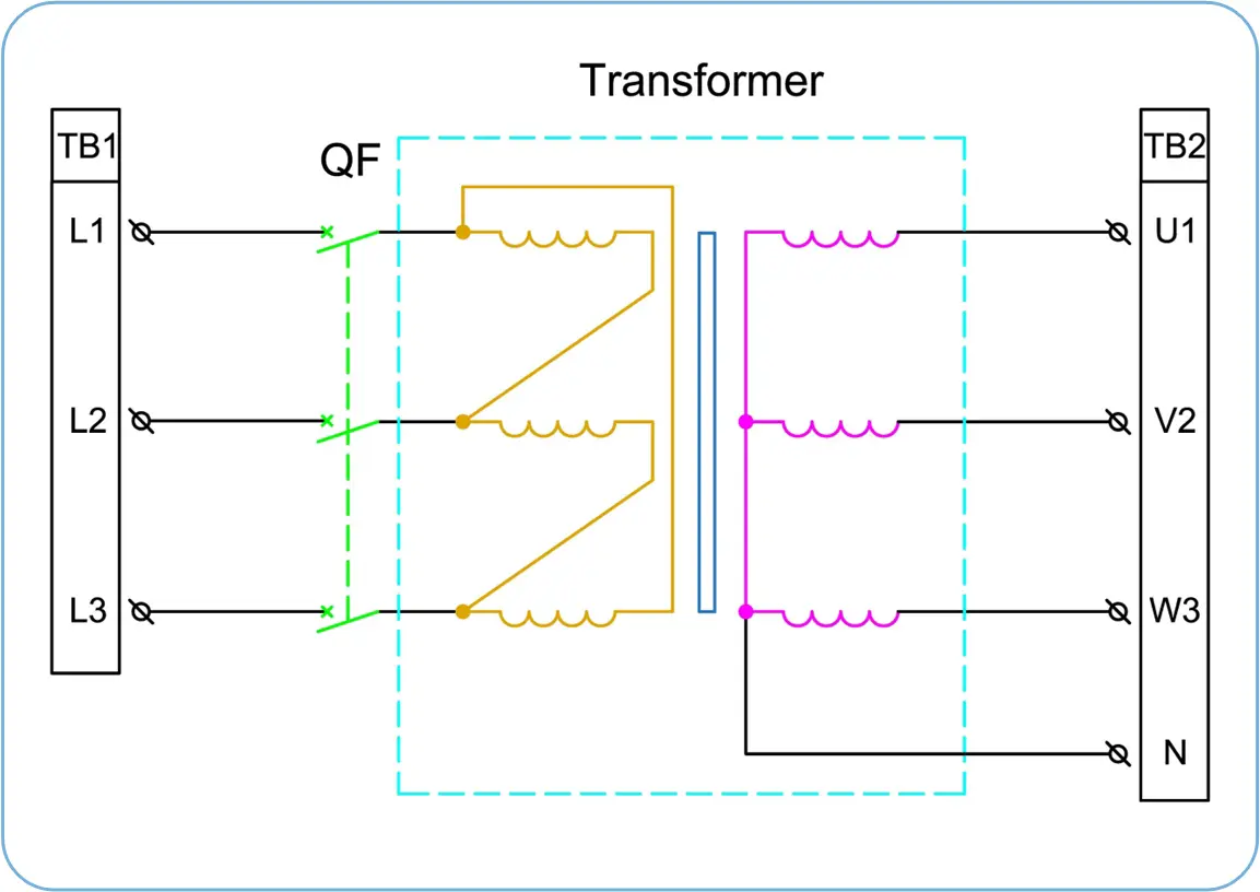
A three-phase isolation transformer uses separated primary and secondary windings to provide galvanic isolation between input and output circuits.
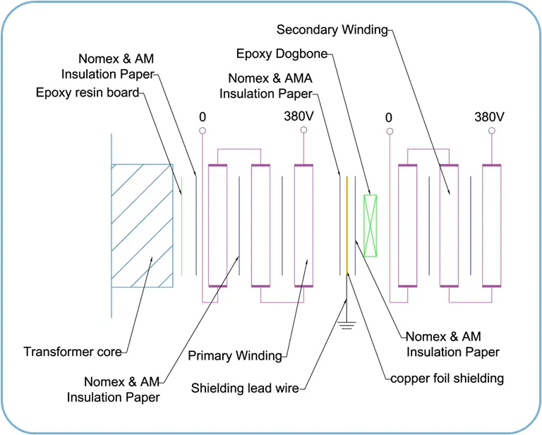
The transformer design includes primary winding, secondary winding, insulation layers and shielding components to improve electrical safety and reduce electrical interference.
Selected installations using Winzele three-phase isolation transformers for voltage adaptation and equipment protection.
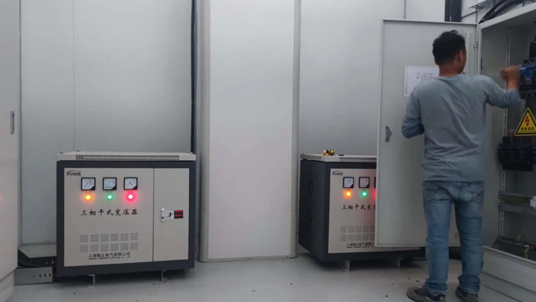
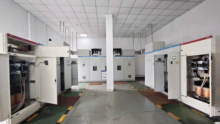
Looking for a similar project?
Explore more real installations by equipment, industry and capacity.
| Parameter | Specification |
| Product Model | SG-Series Dry-Type Isolation Transformer |
| Rated Capacity (KVA) | 3KVA-2500KVA |
| Number of Phases | 3 Phases |
| Rated Frequency (Hz) | 50/60Hz |
| Cooling Method | Temperature Control Forced Air Cooling |
| Installation Location | Indoor |
| Protection Level (IP Class) | IP20 Indoor, IP33 Outdoor can be customized |
| Color | RAL7035, other colors can be customized |
| Parameter | Specification |
| Input Voltage (VAC) | Three-phase 380V&400V&440V&480V,Other custom voltages are less than 1140V. |
| Output Voltage (VAC) | 380V 415V 220V 200V and other customer specified voltages |
| System Maximum Operating Voltage (V) | 1140V |
| Winding Material | All Copper Wire Wrapped Wire |
| Connection Group | DYn11 YYn0 and other customer specified connection groups |
| Insulation Class | H, F, B |
| Insulation Level | Power Frequency Withstand Voltage 3KV, No Breakdown and No Flashover |
| Overload Capacity | 2 Times Rated Current, Maintain 1 Minute |
| Short-circuit Impedance | <3.5% |
| Magnetic Flux Density | Magnetic flux density ≤1.58T |
| Display Function | Input and output voltage and current display, temperature display |
| Parameter | Specification |
| No-load Loss | According to standard IEC 60076-11:2018 |
| Load Loss | According to standard IEC 60076-11:2018 |
| Noise | 55dB |
| Parameter | Specification |
| Dimensions | See the table below |
| Cable Entry Method | Transformer high and low voltage lead-in method: cable in and out from the bottom |
| Installation Method | Foot-mounted fixed installation |
| Lifting Method | Bottom forklift lifting |
| Relative Humidity | 10%~90% RH |
| Altitude | Below 3000 meters Capacity derated by 10% for every 1000 meters increase in altitude |
| Ambient Temperature | -25~+55℃ Maximum daily average temperature: 35℃ |
| Parameter | Specification |
| Implementation Standard | IEC 60076-11:2018 |
| Earthquake Resistance | Ground horizontal acceleration 0.2g, vertical acceleration 0.1g |
| Use Environment | The installation location is free of severe steam, chemical deposition, dust and explosives, etc. |
| Other special requirements can be communicated with winzele | |
Transformer manufacturing involves multiple controlled processes, including material preparation, core assembly, winding, insulation treatment, final assembly and electrical testing.
Transformer production starts with controlled raw materials including silicon steel and copper winding conductors. Silicon steel sheets are precisely processed before core assembly.
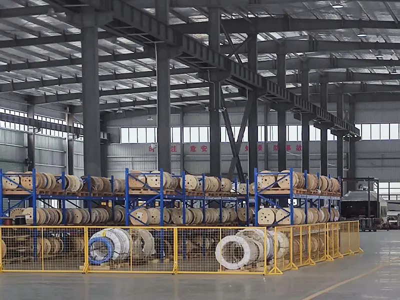
Transformer production starts with controlled raw materials including silicon steel sheets and copper conductors prepared according to design requirements.
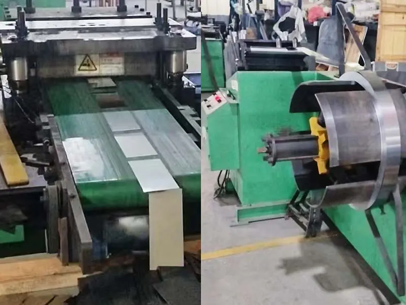
Precision cutting of silicon steel sheets helps ensure accurate core dimensions and magnetic performance.
Transformer cores are assembled with controlled lamination stacking to achieve proper magnetic performance.
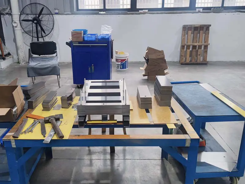
Proper stacking techniques reduce magnetic loss and improve transformer efficiency.
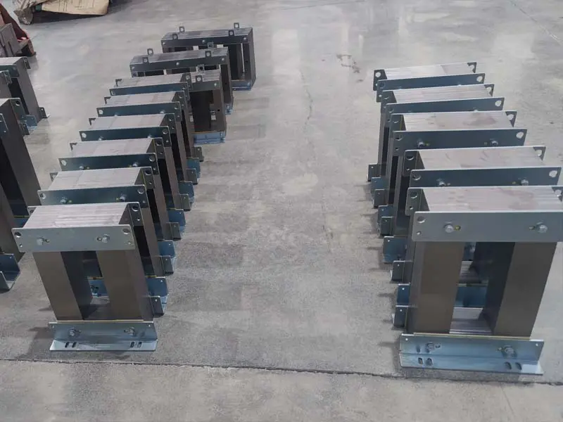
Core components are assembled with controlled lamination stacking to optimize magnetic performance.
Different winding technologies including wire winding and copper foil winding are applied according to transformer design requirements.
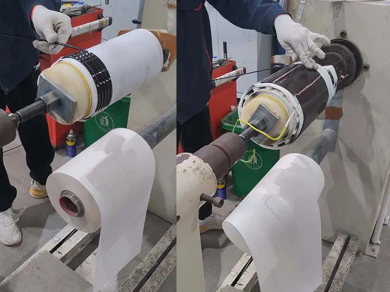
Copper conductors are wound according to electrical design requirements to ensure reliable current carrying performance.
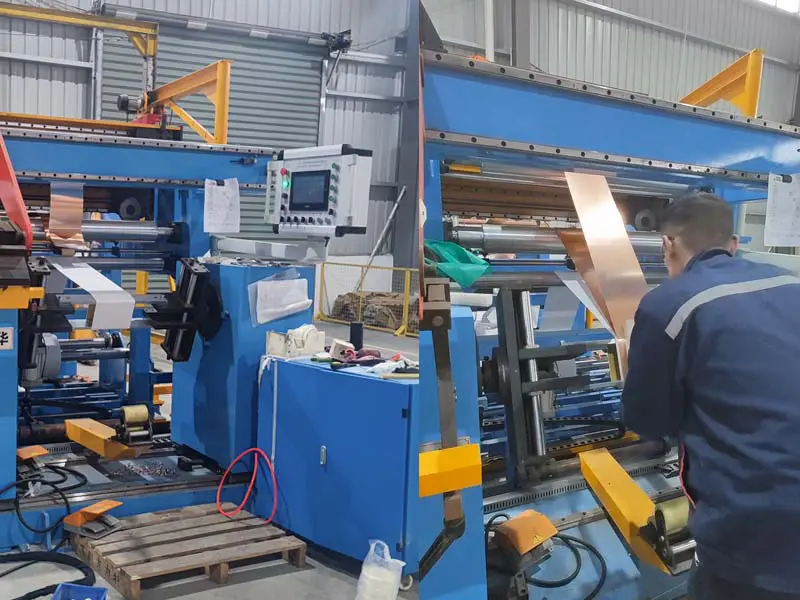
Copper foil winding technology provides stable electrical characteristics for high-current transformer applications.
Vacuum pressure impregnation is an important insulation treatment process for dry-type isolation transformers. The process removes air and moisture from winding insulation structures, improves insulation strength, mechanical stability and long-term operating reliability.
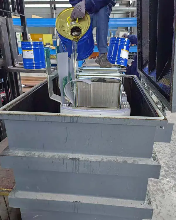
Transformer windings are prepared for vacuum pressure impregnation to improve insulation performance.
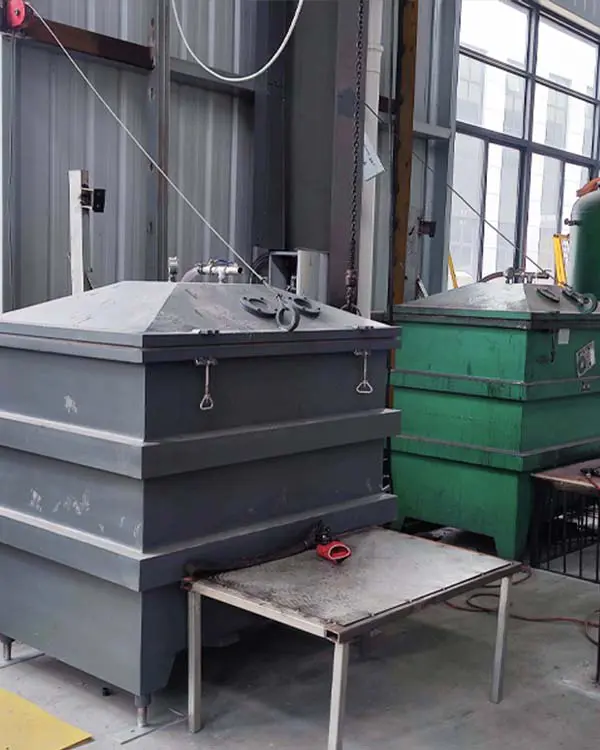
During VPI processing, insulating varnish penetrates winding insulation layers under controlled vacuum conditions.
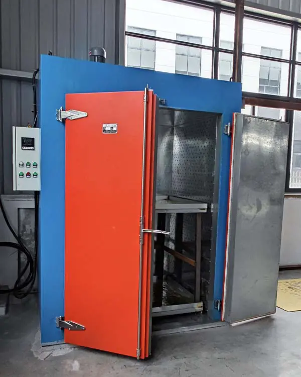
Controlled drying removes moisture and stabilizes the insulation system after impregnation.
The transformer assembly process integrates completed windings, magnetic cores, insulation components and mechanical structures into a complete dry-type isolation transformer. Each assembly step is controlled to ensure proper electrical performance, mechanical strength and long-term reliability.
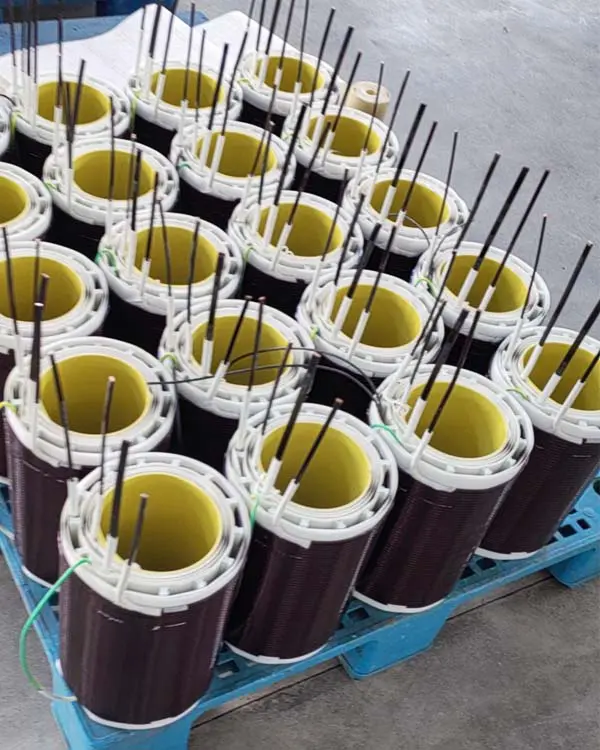
Completed windings are prepared for integration with transformer cores and mechanical components.
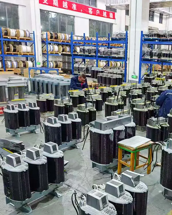
Transformer windings and magnetic cores are assembled according to the designed structure and electrical requirements.
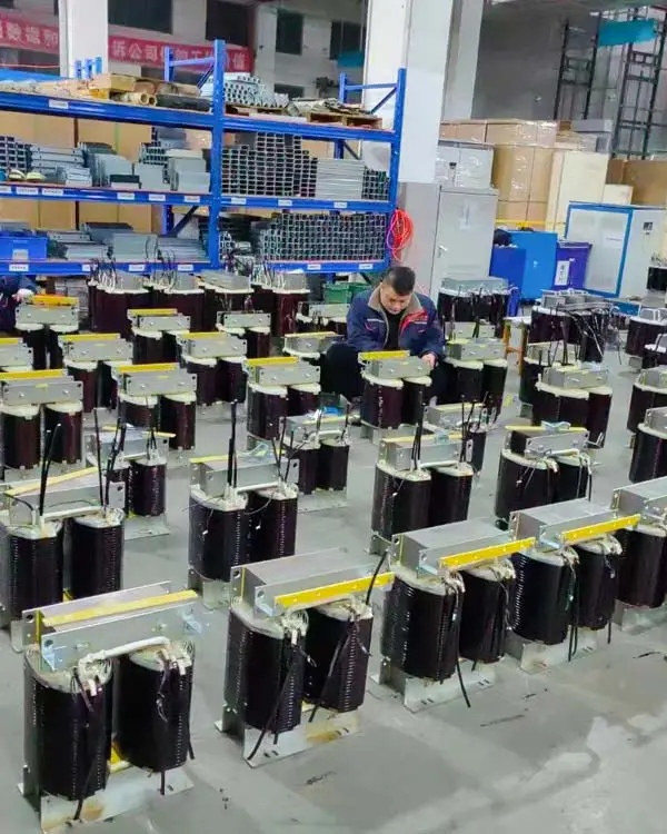
Fully assembled transformers undergo inspection before electrical testing and final shipment.
Each transformer undergoes electrical testing to verify winding performance, insulation strength and thermal reliability before shipment.
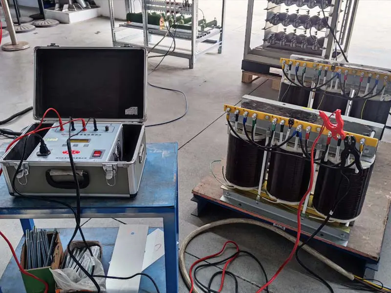
Electrical parameters are tested to verify winding performance and transformer characteristics.
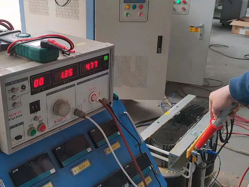
AC withstand voltage testing verifies insulation strength between windings and ground.
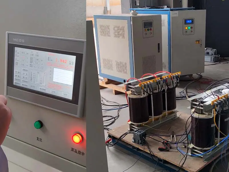
Automated testing equipment records electrical parameters and verifies transformer performance.
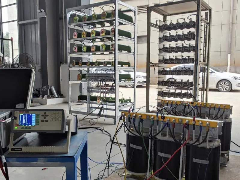
Load testing evaluates thermal performance under operating conditions.
PDU applications (CT / DR / MRI): Isolation transformers are commonly used in power distribution units (PDUs) for CT, DR and MRI systems to provide electrical separation and a reliable power interface for medical imaging equipment..
Electrical isolation purpose: The transformer helps separate the equipment circuit from the upstream power supply and supports stable operation of sensitive medical imaging systems. The final safety performance depends on the complete power distribution design, protective grounding, safety devices and the requirements of the equipment manufacturer.
Machining centers and CNC lathes: serves as an isolated power interface at the rectification front end of precision servo control equipment such as machining centers and CNC lathes.
Precision equipment: effectively suppresses interference signals on the power supply of the precision equipment.
Imported equipment: converts the local 380V supply to the voltage standards of imported equipment — Japanese 200V/220V, US 480V and European 400V — to meet the domestic operation needs of the equipment.
Exported equipment: converts foreign 200V/220V, 480V and 400V supplies to 380V, providing voltage compatibility for exported equipment operating at the local supply standard.
Analytical instruments and laboratory equipment: Safety isolation provides electrical separation between the equipment and the supply system, helping improve operator protection when combined with proper grounding and protective devices..
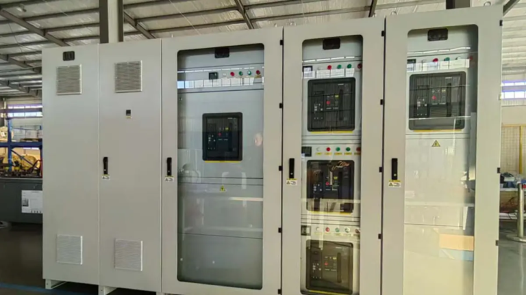
Industrial bypass isolation cabinets: The isolation transformer can help reduce neutral-to-ground voltage issues and common-mode disturbances depending on the grounding system, shielding design and installation conditions.
△/Y connection creating a new neutral point: the three-phase dry-type isolation transformer uses a △/Y connection and generates a new neutral line (zero line), making the equipment independent of the neutral line of the power grid.
Avoiding abnormal operation caused by poor grid neutral conditions: because the equipment no longer depends on the neutral line of the power grid, abnormal operation caused by a poor grid neutral is avoided.
Reducing zero-ground voltage problems: The isolation transformer output can help reduce excessive neutral-to-ground voltage issues when the secondary neutral and grounding system are properly designed.
Third harmonic isolation: When significant third harmonic components are present in the power system, a Delta/Wye connected isolation transformer can provide a path for triplen harmonic currents and help reduce their propagation to the upstream power system when properly designed.
Interference and common-mode disturbance reduction: the isolation transformer reduces interference signals between the power grid and the connected equipment.
Nonlinear load harmonic isolation: can help limit the propagation of certain harmonic currents from nonlinear loads, depending on transformer impedance, connection method and system design.
Control system sampling interference: nonlinear load current distortion can affect sampling accuracy; sampling at the input end of the Yo/△ isolation transformer provides a control signal that reflects the actual situation, so the voltage-stabilized power supply can be controlled normally.
UPS input isolation transformer (△/Yo): connect an isolation transformer to the input end of the UPS and its power supply.
Bypass safety isolation: After the isolation transformer is connected, the secondary winding is magnetically coupled with the primary winding while remaining electrically separated. This configuration provides an isolated power interface and improves system safety when combined with proper grounding and protection measures.
UPS output isolation transformer (Yo/△): Connect an isolation transformer to the output end of the UPS and the power supply:
The output isolation transformer can help reduce the influence of nonlinear load current distortion on the operation of the voltage-stabilized power supply and limit the propagation of certain disturbances to the upstream power system when properly designed and applied.
For unbalanced loads, a Yo/△ connection can help maintain stable operation of the voltage-stabilized power supply when the transformer capacity, connection method and system design are properly selected.
Mechanical drawings provide installation reference dimensions for three-phase isolation transformer integration.
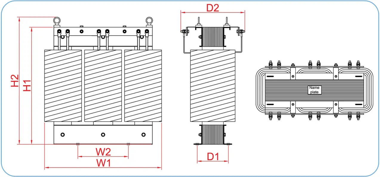
Available capacities, dimensions and enclosure options for three-phase dry-type isolation transformers.
| Model | Rated Capacity (kVA) | Transformer Dimensions W×D×H (mm) | Enclosure Dimensions W×D×H (mm) |
| SG-3KVA | 3 | 240 × 130 × 230 | 400 × 260 × 380 |
| SG-5KVA | 5 | 290 × 160 × 270 | 450 × 300 × 420 |
| SG-7.5KVA | 7.5 | 330 × 250 × 360 | 490 × 360 × 460 |
| SG-10KVA | 10 | 400 × 236 × 390 | 490 × 360 × 460 |
| Model | Rated Capacity (kVA) | Transformer Dimensions W×D×H (mm) | Enclosure Dimensions W×D×H (mm) |
| SG-15KVA | 15 | 460 × 280 × 400 | 560 × 380 × 560 |
| SG-20KVA | 20 | 440 × 300 × 420 | 620 × 400 × 570 |
| SG-25KVA | 25 | 440 × 300 × 420 | 600 × 430 × 590 |
| SG-30KVA | 30 | 530 × 320 × 420 | 600 × 430 × 590 |
| SG-35KVA | 35 | 560 × 320 × 420 | 690 × 460 × 590 |
| SG-40KVA | 40 | 580 × 355 × 500 | 730 × 450 × 600 |
| SG-50KVA | 50 | 630 × 350 × 450 | 750 × 495 × 695 |
| SG-60KVA | 60 | 650 × 400 × 540 | 800 × 495 × 700 |
| SG-80KVA | 80 | 700 × 400 × 665 | 820 × 550 × 700 |
| SG-100KVA | 100 | 810 × 430 × 670 | 900 × 560 × 860 |
| SG-125KVA | 125 | 830 × 430 × 690 | 1000 × 600 × 880 |
| SG-160KVA | 160 | 840 × 460 × 800 | 1010 × 610 × 940 |
| SG-200KVA | 200 | 855 × 500 × 800 | 1050 × 650 × 1050 |
| SG-250KVA | 250 | 1000 × 510 × 950 | 1200 × 650 × 1150 |
| Model | Rated Capacity (kVA) | Transformer Dimensions W×D×H (mm) | Enclosure Dimensions W×D×H (mm) |
| SG-350KVA | 350 | 1000 × 600 × 1000 | 1300 × 750 × 1200 |
| SG-400KVA | 400 | 1100 × 650 × 1050 | 1400 × 800 × 1250 |
| SG-500KVA | 500 | 1150 × 700 × 1100 | 1500 × 850 × 1300 |
| SG-630KVA | 630 | 1250 × 750 × 1200 | 1600 × 900 × 1400 |
| SG-800KVA | 800 | 1350 × 800 × 1300 | 1700 × 950 × 1500 |
| SG-1000KVA | 1000 | 1450 × 850 × 1400 | 1800 × 1000 × 1600 |
| SG-1250KVA | 1250 | 1550 × 950 × 1500 | 1900 × 1100 × 1700 |
Standard models are available up to 1250 kVA. For higher capacity requirements, including projects above this range, please contact Winzele engineering team for customized transformer design and evaluation.
Contact our sales team for pricing, technical specifications, and delivery information.