

How to Size an Active Harmonic Filter (AHF): Current Calculation & Selection Guide
An active harmonic filter (AHF) is selected by its required compensation current in amperes, not by transformer kVA, load kW, or main breaker rating.
This guide explains the active harmonic filter sizing and capacity calculation process, from harmonic-current measurement and THDi to engineering margin and practical AHF selection.
Quick Answer / Quick Formula
For harmonic-only compensation (preliminary estimate):
Ih ≈ I1 × THDi
Recommended AHF current: I_AHF ≈ Ih × K
Where:
- I1 = fundamental (load) current, A
- THDi = current total harmonic distortion (as a decimal, e.g. 25% = 0.25)
- Ih = estimated harmonic compensation current, A
- K = project-specific engineering margin factor
A preliminary engineering margin of approximately 15–30% is commonly considered for load variation, operating uncertainty and measurement uncertainty. Future expansion should be evaluated separately according to the project plan. This is a first-pass method, not an absolute rule — final selection should also check the harmonic spectrum, phase imbalance, neutral current, existing capacitor banks, the target THDi, and future load growth.
1. Define the Compensation Scope
Before calculating any value, define what the AHF will compensate:
- Individual nonlinear load — e.g., one frequency converter, rectifier, or large UPS; measure at that equipment’s input terminals.
- A group of nonlinear loads — e.g., several converters on one production line; measure at the common busbar feeding the group.
- Entire distribution system / busbar — compensate the total harmonic current from all loads on the busbar; measure at the target PCC / main distribution bus.
The measurement point and the AHF installation point must correspond to the intended compensation scope. A value measured at one location does not automatically apply to another.
2. Measure the Harmonic Load
The recommended basis for sizing is an actual measurement with a power quality analyzer (e.g., Fluke, Hioki, YOKOGAWA, or equivalent) at the target compensation point.
Parameters to record:
| Parameter | Description |
|---|---|
| RMS current | Total RMS current at the measurement point |
| Fundamental current I1 | RMS value of the fundamental (50/60 Hz) component, A |
| THDi | Ratio of total harmonic current RMS to fundamental current RMS, % |
| Individual harmonic orders | I5, I7, I11, I13, etc. (A or %) — useful for control strategy and resonance checks |
| Voltage / power factor | System voltage and load power factor during measurement |
| Load operating condition | Which machines / processes were running during measurement |
Measurement discipline:
- Measure under several representative operating conditions, and identify the condition with the highest required harmonic compensation current (I1 × THDi), rather than relying on the highest THDi value alone — THDi must always be evaluated together with the fundamental current.
- The measurement duration should cover at least one full load operating cycle.
- For three-phase four-wire systems, also check the neutral current (see Section 7).
New to AHF applications? Our harmonic mitigation solutions give an overview of where active filters are used in industrial systems; this guide focuses on the sizing calculation.
Typical THDi Values for Preliminary Estimation
If field measurement is not yet available, first check the drive, UPS, rectifier or other nonlinear-load manufacturer’s documentation for specified input THDi, harmonic spectrum, or input-current characteristics. If neither measurement nor equipment-specific data is available, the typical values below may be used only for preliminary estimation:
| Load Type | Typical THDi Range |
|---|---|
| 6-pulse rectifier without reactor | approx. 30–50% |
| 6-pulse rectifier with DC reactor | approx. 30–40% |
| 6-pulse rectifier with AC reactor | approx. 30–35% |
| 12-pulse rectifier | approx. 10–15% |
| UPS / rectifier load | approx. 25–40% |
These values are for preliminary estimation only. Actual THDi depends on the equipment design, loading level, reactor / choke configuration, and system impedance. Field measurement is preferred for final AHF sizing. High-frequency switching power supplies can show very high THDi (>80%), but a high THDi does not necessarily mean high harmonic current if the fundamental current is small.
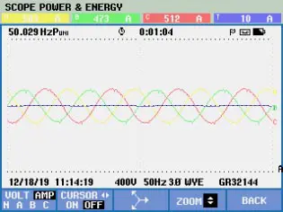
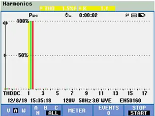
A field measurement provides more useful sizing information than load nameplate data alone. The example below shows how both the current waveform and harmonic spectrum can change before and after AHF compensation.
Example Power Quality Measurement Before and After AHF Compensation
| Measurement | Before AHF Compensation | After AHF Compensation |
|---|---|---|
| Current Waveform | 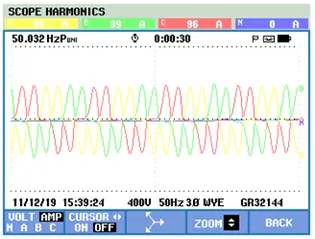 |
 |
| Harmonic Spectrum | 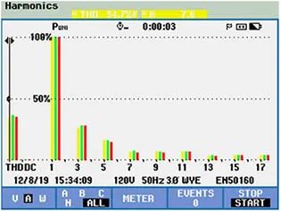 THDi ≈ 34.7% |
 THDi ≈ 1.5% |
Example current waveform and harmonic spectrum measurements before and after AHF compensation. In this measurement, THDi decreased from approximately 34.7% to 1.5%. Actual compensation performance depends on the system conditions, load characteristics, AHF configuration, and measurement point.
3. Calculate Fundamental and Harmonic Current
From apparent power
I = S / (√3 × U)
Where S is the apparent power in VA (or kVA, converted consistently), and U is the line-to-line voltage in V.
From active power
I = P / (√3 × U × PF)
Where P is the active power in W (or kW, converted consistently), U is the line-to-line voltage in V, and PF is the power factor.
Why both formulas exist: S (apparent power) already includes the reactive component, so it must not be divided by PF again. P (active power) excludes it, so it must be divided by PF to recover the full line current. Using the wrong formula gives the wrong fundamental current — and therefore the wrong AHF size.
Estimate harmonic current
Once I1 and THDi are known:
Ih ≈ I1 × THDi
When THDi is measured relative to the fundamental current, the total harmonic RMS current is obtained from Ih = I1 × THDi. Example: a frequency converter with measured fundamental current I1 = 100 A and THDi = 40% → Ih = 100 × 0.40 = 40 A. The AHF must provide at least 40 A of harmonic compensation for this load.
The individual harmonic spectrum should still be reviewed to identify the dominant harmonic orders, confirm that they fall within the intended AHF compensation range, and evaluate system conditions such as capacitor-bank interaction or other harmonic-related risks. For a practical overview of AHF units in the field, see our article on active harmonic filter applications.
4. Reactive Compensation and Engineering Margin
Harmonics only: the sizing input is Ih from Section 3.
Harmonics + reactive current (to improve power factor): obtain the reactive current Iq from the power-quality measurement, or calculate it from measured active/reactive power and the displacement power factor. For nonlinear loads, total power factor is not always equal to displacement power factor (cos φ), so a simplified sin φ estimate is not reliable here. Combine the two components:
Ic = √(Ih² + Iq²)
Where Ih = harmonic compensation current, Iq = reactive compensation current, and Ic = total compensation current the AHF must deliver.
An AHF is not a substitute for all reactive power compensation. If the system needs a large, steady reactive correction, a dedicated compensator (capacitor bank / SVG) may be more economical, with the AHF handling harmonics and fast-varying compensation.
Add an engineering margin to the calculated compensation current to cover load fluctuation, operating variation, and measurement uncertainty. A preliminary margin of approximately 15–30% may be considered for initial sizing. Future expansion should be evaluated separately according to the project plan:
I_AHF = Ih × K (harmonics only)
I_AHF = Ic × K (harmonics + reactive)
Where K is a project-specific total design factor (in the example in Section 5, K = 1.3 reflects that project’s design assumptions). Some AHF models have short-term overload capacity (e.g., 150% for 1 minute), but the rated capacity must be sufficient for continuous operation.
5. Complete AHF Sizing Example
System data (measured under the operating condition requiring the highest harmonic compensation current):
- System voltage: 380 V
- Fundamental current I1: 800 A
- THDi: 25%
- Harmonic compensation only (target power factor acceptable)
- Margin: 20% load fluctuation + 10% expansion → K = 1.3
The margin components above are design assumptions for this example only; the applicable margin factor is project-specific and should be agreed with the supplier.
Calculation:
- Harmonic current: Ih = 800 A × 25% = 200 A
- With margin: I_AHF = 200 A × 1.3 = 260 A
- Recommended rating: the next standard total capacity ≥ 260 A → 300 A
| Parameter | Value |
|---|---|
| System Voltage | 380 V |
| Fundamental Current | 800 A |
| THDi | 25% |
| Estimated Harmonic Current | 200 A |
| Design Margin | 30% |
| Required Compensation Current | 260 A |
| Recommended AHF Total Capacity | 300 A |
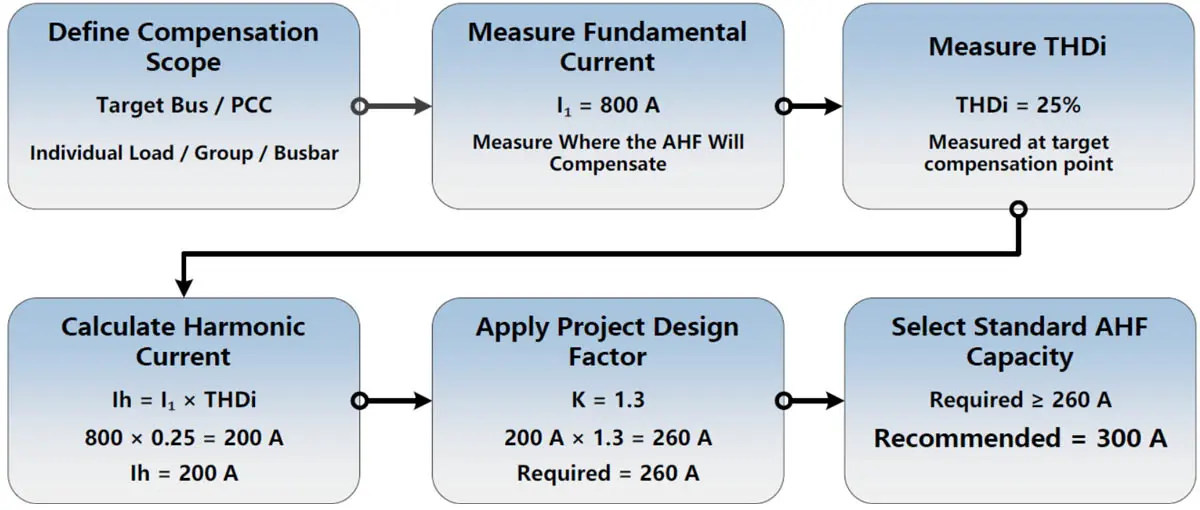
AHF sizing calculation example showing how 800 A fundamental current and 25% THDi result in a recommended total AHF capacity of 300 A.
6. Selecting Standard AHF Capacity
A calculated requirement of 260 A does not mean a single 260 A AHF must exist — standard modules are combined to reach the required total capacity.
Winzele AHF standard module ratings (verified from the live product page):
30 A / 50 A / 75 A / 100 A / 150 A
For a calculated requirement of 260 A, the selected total installed AHF capacity should be at least 260 A — in practice, the next standard total capacity is 300 A, using an appropriate combination of standard modules subject to the manufacturer’s parallel-operation limits and cabinet configuration. Confirm the parallel arrangement and cabinet type with the supplier for the specific busbar layout and expansion plan.
Module ratings are based on the current Winzele AHF product specification. Parallel-operation limits, cabinet configuration and derating conditions should be confirmed for the specific project.
Ambient temperature: check the manufacturer’s ambient-temperature derating requirements before finalizing the rated current. If the installation temperature exceeds the rated operating condition, additional capacity or derating may be required. The Winzele AHF product page lists an ambient temperature range of -25 to 55 °C; confirm the applicable derating curve with the factory for the actual installation environment.
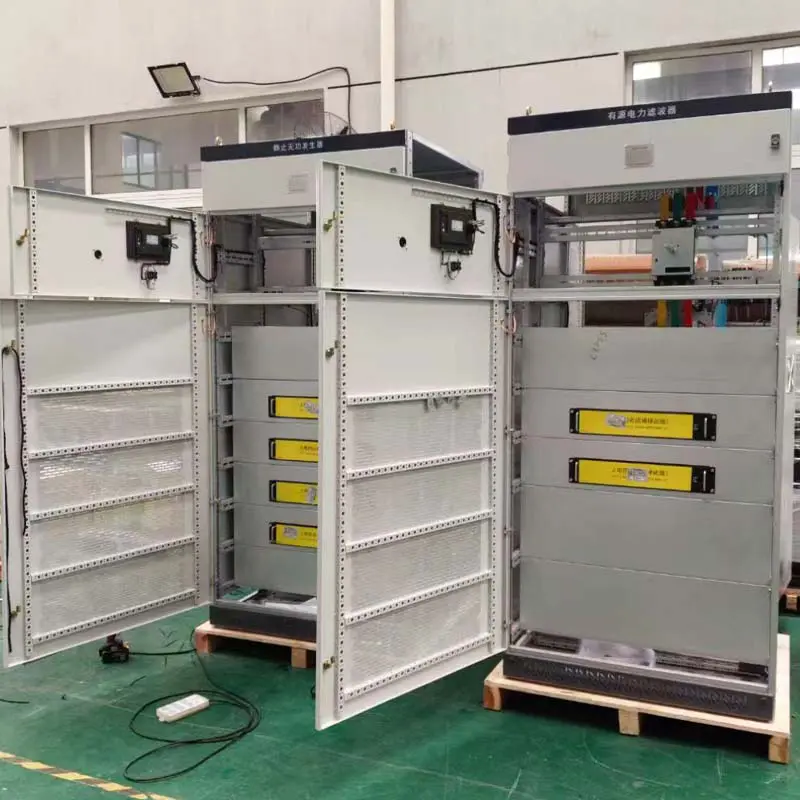
Example AHF cabinet integration using multiple standard modules to achieve the required total compensation capacity.
Related product: Active Harmonic Filter (AHF)
7. 3P3W, 3P4W and System Voltage Considerations
Wiring system. In 3P3W (three-phase three-wire) systems, focus on the phase harmonic currents from three-phase nonlinear loads (VFDs, rectifiers). In 3P4W (three-phase four-wire) systems, additionally check:
- Neutral current — triplen harmonics (3rd, 9th, 15th…) from single-phase nonlinear loads and phase imbalance add up in the neutral
- Single-phase nonlinear loads — e.g., switched-mode power supplies, lighting
- Phase imbalance — unbalanced loads increase the required compensation capacity
Do not assume “3P4W always needs a bigger AHF.” The extra capacity is driven by the measured neutral current and triplen harmonic content, not by the wiring system alone.
System voltage. An AHF rating is not only “how many amps” but also “at what voltage.” Confirm the rated system voltage (e.g., 200 V / 220 V / 380 V / 400 V / 480 V / 690 V), allowable voltage range (e.g., ±10%), wiring system, and frequency (50/60 Hz) with the supplier. Three-phase 200 V and 220 V supply systems exist in several regional markets (for example, Japan at 200 V and parts of Asia at 220 V), so the AHF voltage rating must be verified against the actual system voltage. The Winzele AHF product page lists rated voltages of 200 V / 220 V / 400 V / 480 V / 690 V. For the Winzele AHF series described here, 380 V and 400 V systems use the 400 V-rated configuration. Other manufacturers may use different voltage-rating conventions, so always confirm the rated voltage against the actual system before selection.
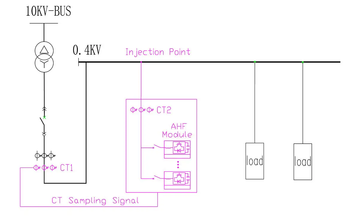
AHFs for this type of current compensation are normally connected in parallel with the load or bus to be compensated — matching the AHF parallel injection connection shown on the Winzele AHF product page.
The CT installation position should match the compensation scope defined earlier in the sizing process.
Typical AHF CT Installation and Injection Point Configurations
| Main-Bus CT Installation | Load-Side CT Installation |
|---|---|
 |
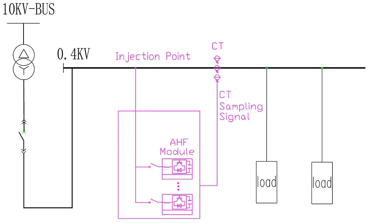 |
Typical AHF connection examples showing main-bus and load-side CT installation arrangements. The CT sampling position and AHF injection point should be selected according to the intended compensation scope, system topology, and control configuration.
8. Information Required for AHF Selection
Before requesting a quotation, prepare:
| Required Information | Example |
|---|---|
| System Voltage | 400 V / 480 V |
| Wiring System | 3P3W / 3P4W |
| Fundamental Current | 800 A |
| THDi | 25% |
| Harmonic Spectrum | 5th / 7th / 11th / 13th |
| Main Load Type | VFD / UPS / Rectifier |
| Existing Capacitor Bank | Yes / No |
| Target Harmonic Level | Project Requirement |
| Future Load Expansion | 10–20% |
| Ambient Temperature | Project Condition |
Example values are illustrative only — they vary from project to project. Supplying these data (ideally with a power quality measurement report) lets the supplier provide a professional selection instead of a guess.
9. Common AHF Sizing Mistakes
- Selecting the AHF directly from the transformer kVA rating or the breaker current
- Ignoring the actual THDi and estimating harmonics from nameplate values alone
- Ignoring the harmonic spectrum, especially where capacitor banks create resonance risk
- Ignoring neutral current in 3P4W systems or existing capacitor banks
- No margin for future load growth
- Assuming one standard AHF rating fits every project
10. FAQ
How many amps of AHF do I need?
Estimate Ih ≈ I1 × THDi from the measured fundamental current and THDi, add an engineering margin (commonly 15–30%), and select the next standard total capacity above the result.
Can AHF capacity be calculated from THDi?
As a preliminary estimate, yes: Ih ≈ I1 × THDi. It gives the harmonic current magnitude but not the spectrum; confirm with the individual harmonic orders and the actual measurement for a final selection.
Should AHF current equal the total load current?
Usually not. It should match the harmonic (and any specified reactive) current to be compensated — using the full load current typically results in an oversized, more expensive unit.
Does a 480 V system require a different AHF?
Yes. The AHF voltage rating must match the system voltage (e.g., 400 V vs 480 V vs 690 V). Always confirm voltage rating, wiring system, and frequency with the supplier.
Can multiple AHF modules operate in parallel?
Yes, standard modules can be combined in parallel to reach the required total capacity. Confirm the parallel-operation configuration, communication, and cabinet arrangement with the supplier.
Related AHF Project Cases
Active Harmonic Filter Solution for Ningxia Monocrystalline Silicon Manufacturing Plant
AHF harmonic mitigation project for a semiconductor manufacturing power system supplied by 2000 kVA transformers, with field measurements showing a significant reduction in current harmonic distortion (THDi from approximately 30.41% to 2.98%).
Active Harmonic Filter Retrofit and Capacity Upgrade for a Hong Kong Commercial Building
AHF retrofit and capacity upgrade project for a commercial building power distribution system, using 6 × 150 A wall-mounted units (900 A total) in parallel to restore harmonic mitigation capability.


