Leading Manufacturer Of Voltage Stabilizers(AVR) & low-Voltage transformers+8613916759436[email protected]


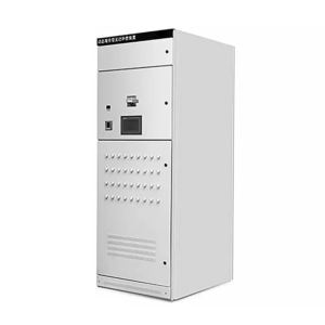
Dynamic filtration reactive compensation devices are designed for electrical systems where the reactive power demand changes frequently and the harmonic environment must be considered when applying capacitor compensation. These systems combine automatic power factor correction with fast switching and properly matched capacitor-reactor branches. They are commonly used with fluctuating industrial loads where conventional fixed capacitor banks or contactor-switched systems may not provide a sufficiently fast or reliable response.
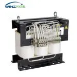
In a thyristor-switched capacitor system, the controller continuously monitors the power factor and reactive power demand. It then connects or disconnects the required capacitor steps through thyristor switching modules. Each compensation step includes a series detuned reactor as standard. The reactor is not intended to perform active harmonic filtering; its primary purpose is to prevent harmful interaction between the capacitor bank and the electrical network, suppress harmonic amplification, limit switching inrush, and protect the compensation components.
A capacitor bank changes the impedance characteristics of the electrical system. If capacitors are installed without reactors in a network containing harmonic-producing loads, the capacitors and the upstream transformer or source impedance may create a parallel resonance near an existing harmonic frequency. Under these conditions, harmonic current or voltage can be amplified instead of reduced. The resulting current stress can cause capacitor overheating, fuse operation, premature ageing, nuisance tripping, and unstable compensation performance.
Adding a correctly selected series detuned reactor shifts the resonance point of the capacitor branch away from the harmonic frequencies that require protection. This reduces the risk of harmonic amplification and controls the current passing through the capacitors. The reactor also limits the inrush current that occurs when a capacitor step is energized. For dynamic systems using thyristor switching, the reactor, capacitor, semiconductor switch, fuse, conductor, ventilation, and controller settings must therefore be engineered as one coordinated branch.
| Capacitor Compensation Without Reactors | Compensation With Matched Detuned Reactors |
|---|---|
| May form a parallel resonance with the transformer and system impedance. | Moves the branch resonance away from the harmonic frequencies selected during system design. |
| Existing harmonic currents may be amplified and attracted into the capacitor bank. | Helps suppress harmonic amplification and reduces excessive harmonic loading of the capacitors. |
| Capacitors may experience higher RMS current, overheating, dielectric stress, or shortened service life. | Reduces capacitor stress and supports more stable long-term operation when the branch is correctly rated. |
| Switching inrush can place additional stress on capacitors, switching devices, and protective components. | The series reactor limits inrush current and helps protect the complete switching branch. |
| Suitable only where a system study confirms that harmonic and resonance risks are acceptably low. | Better suited to industrial networks with nonlinear loads, subject to correct harmonic assessment and reactor matching. |
Winzele systems can be configured with 7% or 14% detuned reactors according to the measured harmonic spectrum, system impedance, load characteristics, and project requirements. These ratios are not interchangeable options selected only by preference, and a higher percentage is not automatically better.
A 7% reactor is commonly considered for industrial networks where detuning below the fifth harmonic is required and the third-harmonic content is not the governing concern. A 14% reactor provides stronger detuning and may be considered where significant third-harmonic content or other system conditions require the resonance point to be placed below the third harmonic. This is a general application distinction only; the final ratio should be confirmed from site measurements or an engineering harmonic assessment.
The reactor ratio also affects the voltage across the capacitor at the fundamental frequency. For this reason, the capacitor voltage rating and kvar output must be matched to the selected reactor rather than calculated as if the capacitor were connected directly to the busbar. The reactor current rating, thermal design, thyristor capacity, fuse selection, cable size, cabinet ventilation, and protection settings must also be checked for the actual branch current and expected harmonic duty.
Correct matching provides detuned reactive power compensation with improved resistance to harmonic stress. It does not cancel harmonic current in the same way as an active harmonic filter. Where harmonic limits cannot be met by detuned compensation alone, the project may require a separate active or passive filtering solution based on the measured harmonic spectrum.
For reliable selection, the system voltage and frequency, transformer capacity and impedance, load power, existing and target power factor, required compensation capacity, load variation, existing capacitor banks, and available harmonic measurements should be provided. Winzele uses this information to determine the compensation steps, thyristor switching capacity, 7% or 14% reactor configuration, capacitor rating, protection, and cabinet arrangement for the project.
Need a custom solution? Fill out the form below and our team will get back to you within 24 hours.