

Siemens MRI Voltage Stabilizer Solution | 150kVA Voltage Stabilizer Application Case
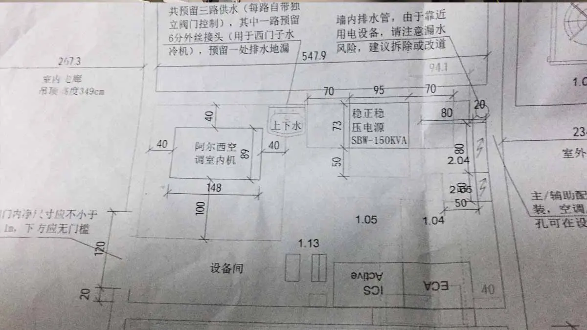
What capacity voltage stabilizer does a Siemens MRI need? This case presents the actual application of a 150kVA Winzele voltage stabilizer (150kVA voltage stabilizer) configured for a Siemens MRI system at a medical imaging facility in China. This capacity is the actual configuration confirmed by the project drawing, which specifies “Winele SBW-150KVA” (Winele stabilized power supply SBW-150KVA).
MRI and CT have different power consumption characteristics: some high-field MRI systems use continuously running superconducting magnets and cryogenic cooling-related systems, and continuous operation places sustained demands on power supply stability; the strong magnetic field environment and auxiliary system requirements give MRI power supply solutions special engineering requirements. The 150kVA stabilizer Winzele configured for this Siemens MRI project is a dedicated stabilization solution tailored to the MRI power environment (MRI Voltage Stabilizer Solutions).
Fig. 1 shows the on-site installation of the Siemens MRI system with the 150kVA Winzele voltage stabilizer: in the MRI room environment, electrical equipment layout must meet the manufacturer’s requirements for magnetic field zones, safety distances and installation conditions. The stabilizer is installed in a dedicated electrical space and supplies stable voltage to the MRI system through the power circuit.
Why MRI Systems Need a Dedicated Voltage Stabilizer
The Siemens MRI is high-precision medical imaging equipment; its electronic systems and related power circuits must be coordinated with the on-site distribution conditions. Unlike conventional electrical loads, MRI systems have explicit requirements for the power environment: a stable power environment is an important part of MRI system operating conditions.
Power supply issues that may exist at actual medical facility sites include: grid voltage fluctuation, changes in on-site power supply conditions, load changes in distribution circuits and regional grid condition differences. Once these factors exceed the equipment’s allowable range, they may affect MRI system operational stability and increase the risk of abnormal equipment shutdown.
An MRI stabilization solution must be evaluated together with the MRI equipment model, input voltage requirements, on-site power supply conditions and grid fluctuation. The stabilizer’s capacity, regulation range and power circuit connection method should be consistent with the project distribution design.
Case: Siemens MRI with Winzele Voltage Stabilizer
Case Overview
Winzele configured a 150kVA Winzele voltage stabilizer for the Siemens MRI system at a medical imaging facility in China. The stabilizer is installed in the MRI equipment power circuit as the voltage regulation stage, providing regulated, stable power to the equipment.
| Equipment | Siemens MRI System |
|---|---|
| Installed Solution | 150kVA Voltage Stabilizer |
| Application | Medical Imaging Facility, China |
| Item | Details |
|---|---|
| Equipment | Siemens MRI System |
| Installed Solution | 150kVA Voltage Stabilizer |
| Application | Medical Imaging Facility, China |
Capacity Basis
The project drawing explicitly specifies “Winele SBW-150KVA” (Winele stabilized power supply SBW-150KVA), which serves as the basis for the actual capacity of this project. This capacity applies only to this project; other MRI projects must be evaluated independently based on equipment requirements and on-site distribution conditions: this capacity cannot be applied merely by equipment type, nor can a universal MRI capacity be derived from this case.
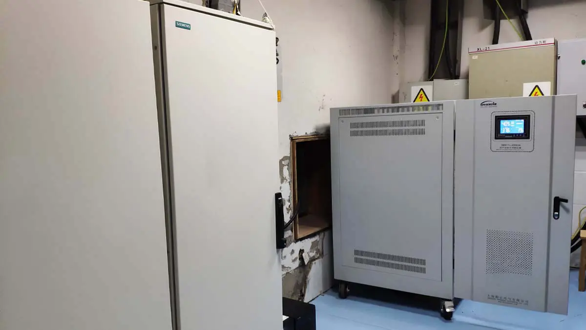
Fig. 1: On-site installation of Siemens MRI system with 150kVA Winzele voltage stabilizer (a medical imaging facility in China)
MRI Room Installation and Electrical Layout Considerations
The MRI scanning area has strong magnetic field characteristics. The room design must be planned as a whole, taking into account the manufacturer’s site requirements, shielding areas, equipment rooms and electrical areas. This is a key engineering feature that distinguishes MRI projects from equipment such as CT.
Stabilization equipment is usually installed in a dedicated electrical space, laid out reasonably relative to the MRI scanning area. The specific installation position, power supply path and equipment room relationships should be determined by the on-site engineering design and coordinated with the MRI room’s electrical planning. In the MRI room environment, electrical equipment layout must meet the manufacturer’s requirements for magnetic field zones, safety distances and installation conditions.
MRI Auxiliary Systems and Power Supply Reliability
Some MRI systems include cryogenic cooling-related systems and other auxiliary equipment (such as cold heads, compressors and monitoring systems). Different systems may have different power circuits, load characteristics and operating conditions, which should be verified separately in the project distribution design.
A stable power environment is an important consideration in overall MRI installation conditions. The stabilization solution should clearly define the power circuits and equipment scope it serves and be coordinated with the auxiliary systems’ distribution design.
Power Supply Characteristics Comparison of MRI, CT and DR Medical Imaging Equipment
| Equipment Type | Main Load Characteristics | Stabilization Focus |
|---|---|---|
| MRI | Some high-field MRI systems include continuously running magnet systems and cryogenic cooling-related auxiliary systems | Power supply continuity, room layout, electrical safety distances |
| CT | Dynamic load changes and peak current demand during scanning | Peak load, voltage fluctuation, power supply stability |
| DR | High power output at the exposure instant, short single exposure time | Exposure peak, intermittent load, voltage stability |
Different medical imaging equipment have different load characteristics; stabilizer capacity and power supply solutions cannot be directly reused across equipment types.
Frequently Asked Questions
Q: Why do MRI and CT need different stabilization solutions?
A: MRI focuses on power supply stability for continuous operation and the room’s electrical layout; CT focuses on dynamic load changes and peak current demand. The two must be evaluated separately.
Project Configuration Summary
| Item | Details |
|---|---|
| Equipment Brand | Siemens |
| Equipment Type | MRI System |
| Installed Equipment | 150kVA Winzele Voltage Stabilizer |
| Application Site | Medical Imaging Facility, China |
| Capacity Nature | Actual configuration for this project (confirmed by drawing); not a universal MRI solution |
Project Status
This case demonstrates the actual application of a Siemens MRI with a 150kVA Winzele voltage stabilizer at a medical imaging facility in China. The project drawing confirms this configuration for this project; this capacity does not represent a universal solution for other Siemens MRI or MRI systems.
Related Medical Equipment Cases
- GE CT Voltage Stabilizer Application Cases
- Siemens CT Voltage Stabilizer Application Cases
- Philips CT Voltage Stabilizer Application Cases
- Siemens MRI Voltage Stabilizer Application
- Canon DR Voltage Stabilizer Application
Related Solutions
Link hierarchy: Medical Solution → MRI Solution → Siemens MRI Case → 150kVA Product Page
Winzele Medical Equipment Voltage Stabilization Solutions
Overseas MRI projects may have different rated voltage, frequency and on-site electrical conditions. The medical imaging power solution (medical imaging power solution) should be engineered and verified against the equipment version, the local power supply system and the application requirements; this project’s parameters cannot be copied directly.
To configure a stabilization solution for a Siemens MRI or other medical imaging equipment, please provide:
- MRI brand and model
- Equipment nameplate parameters
- Rated voltage
- Frequency
- Room electrical conditions
The Winzele engineering team will provide a matched solution based on the project conditions.


