

GE Dual-Slice CT Voltage Stabilization Solution | 120kVA Voltage Stabilizer Application Case
What capacity voltage stabilizer does a GE SpeedLight dual-slice CT need? This project is the actual application of a 120kVA Winzele voltage stabilizer (120kVA voltage stabilizer) configured for a GE dual-slice CT in the medical imaging facility of a small or medium-sized hospital, with a capacity of 120kVA.
Dual-slice CT is a long-serving medical imaging equipment type, commonly involved in scenarios such as continued use, upgrade, maintenance and power supply renovation. For legacy CT equipment, voltage stabilization adaptation focuses on verifying the equipment input requirements, on-site grid conditions and load boundaries — stabilizer capacity must be evaluated together with the specific model, input voltage requirements, on-site power environment and load characteristics.
Fig. 1 shows the on-site application of the GE dual-slice CT with the 120kVA Winzele voltage stabilizer.
GE Dual-Slice CT Equipment Information
The medical equipment brand in this project is GE, and the equipment type is the SpeedLight dual-slice CT.
Why Power Supply Matters for Legacy CT Equipment
The GE dual-slice CT is precision medical imaging equipment; its power supply must be matched to the specific model, equipment input voltage requirements, on-site power environment and load characteristics. For GE dual-slice CT projects still in use, being upgraded, under maintenance or undergoing power supply renovation, the power solution still needs to verify:
- Equipment input voltage requirements
- On-site grid conditions
- Load boundaries
- Stabilization range, output settings and additional functions (determined by the equipment documentation and project electrical conditions)
The Winzele voltage stabilizer acts as the voltage regulation stage in the CT power supply chain, providing regulated power to the connected CT equipment. These legacy equipment projects differ from new installation projects: the equipment has been in service for a long time and the power distribution system often retains its original conditions, so power supply stability depends more on on-site measurement and item-by-item verification.
Case: GE SpeedLight Dual-Slice CT with Winzele Voltage Stabilizer
| Equipment | GE Dual-Slice CT Scanner |
|---|---|
| Installed Solution | 120kVA Winzele Voltage Stabilizer |
| Application | Voltage regulation for connected GE CT medical imaging equipment power circuit |
| Application Site | Medical Imaging Facility, China |
| Configuration Status | Actual project configuration confirmed by project information |
| Item | Details |
|---|---|
| Equipment | GE Dual-Slice CT Scanner |
| Equipment Model | SpeedLight dual-slice CT |
| Installed Solution | 120kVA Winzele Voltage Stabilizer |
| Application | Voltage regulation for connected GE CT medical imaging equipment power circuit |
| Application Site | Medical Imaging Facility, China |
| Configuration Status | Actual project configuration confirmed by project information |
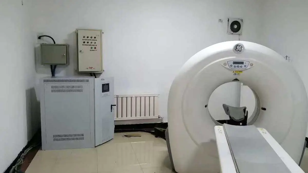
Fig. 1: GE Dual-Slice CT with 120kVA Winzele voltage stabilizer on-site application
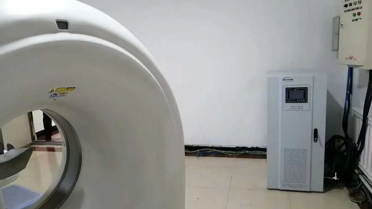
Fig. 2: Installation environment of GE dual-slice CT scanner and Winzele voltage stabilizer
Capacity Notes
A 120kVA Winzele voltage stabilizer was installed on site for voltage regulation in the power supply circuit of the GE dual-slice CT medical imaging equipment; this capacity is the actual configuration for this project.
The capacity of a CT scanner voltage stabilizer (CT scanner voltage stabilizer) cannot be determined solely from the equipment name “dual-slice CT”; it must be confirmed together with the specific model, input voltage requirements, on-site power environment, input power, peak load and load characteristics. Other medical equipment voltage stabilizer (medical equipment voltage stabilizer) projects still need re-evaluation and capacity cannot be copied directly.
Adaptation Scenarios for Legacy CT Equipment and Existing Installations
| Scenario | Key Considerations |
|---|---|
| In-service operation | Verify equipment input requirements, on-site voltage fluctuation, load boundaries |
| Equipment upgrade | Re-verify capacity and power circuit against the upgraded equipment documentation |
| Maintenance | Confirm stabilizer function and range; verify remote monitoring configuration if needed |
| Power supply renovation | Coordinate with on-site distribution design; clarify the circuits and equipment covered by stabilization |
| Used equipment installation (overseas) | Re-design per specific model, rated input voltage and local voltage/frequency; add voltage conversion if needed |
Electrical conditions differ by scenario; each voltage stabilization solution must be verified separately, and capacity configurations from other projects cannot be copied directly.
International Voltage Compatibility
This case is located in China, but the actual input, output and frequency remain subject to the project records. Overseas GE dual-slice CT upgrade, used equipment installation, maintenance or power supply renovation projects should redesign the stabilization range and any necessary voltage conversion based on the specific model, rated input voltage, frequency and site minimum/maximum voltage. Such projects also require evaluation of the CT voltage stabilizer solution against on-site conditions.
Frequently Asked Questions
Q: What capacity voltage stabilizer does a GE dual-slice CT (legacy equipment) need?
A: Stabilizers in the 100-150kVA range are commonly used; this case used 120kVA (actual configuration confirmed by project records), which does not represent a universal capacity for all GE CT or dual-slice CT equipment.
Q: What should be noted when installing a voltage stabilizer for legacy CT equipment during upgrade, maintenance or used equipment installation?
A: Confirm the wiring installation position; if the existing wiring is retained, verify that the stabilizer’s input/output terminal positions are compatible. Re-verify the equipment input requirements, on-site grid conditions and load boundaries. For upgrades, re-evaluate against the upgraded equipment documentation; for overseas used equipment installation, also check the local voltage and frequency and add a voltage conversion scheme if necessary.
Project Configuration Summary
| Item | Details |
|---|---|
| Equipment Brand | GE |
| Equipment Type | Speed Light Dual-Slice CT Scanner |
| Equipment Model | SpeedLight |
| Installed Equipment | 120kVA Winzele Voltage Stabilizer |
| Application | Voltage regulation for GE CT medical imaging equipment power circuit |
| Application Site | Medical Imaging Facility, China |
| Capacity | 120kVA |
Project Status
This case demonstrates Winzele’s engineering application of matching a voltage stabilization solution to the GE SpeedLight dual-slice CT equipment type, the 120kVA actual configuration and the on-site power supply conditions. Figs. 1-4 show the on-site installation environment of the GE dual-slice CT equipment and the Winzele voltage stabilizer at a medical imaging facility in China.
Related Medical Equipment Cases
- GE CT Voltage Stabilizer Application Cases
- Siemens CT Voltage Stabilizer Application Cases
- Philips CT Voltage Stabilizer Application Cases
- Siemens MRI Voltage Stabilizer Application
- Canon DR Voltage Stabilizer Application
Related Solutions
Winzele Medical Equipment Voltage Stabilization Solutions
To configure a voltage stabilizer for a GE SpeedLight dual-slice CT or other medical imaging equipment, please provide the following information. Winzele can evaluate a matched medical imaging power solution (medical imaging power solution) based on the medical equipment documentation and on-site electrical conditions:
- Equipment brand and specific model
- Nameplate power
- Rated input voltage and frequency
- Site minimum and maximum voltage
- Required output voltage
- Whether isolation or voltage conversion is required
The Winzele engineering team will provide a matched voltage stabilization solution based on the project conditions.


