

Two 200 kVA Shore Power Isolation Transformers for Baosteel Meishan Raw-Material Terminal
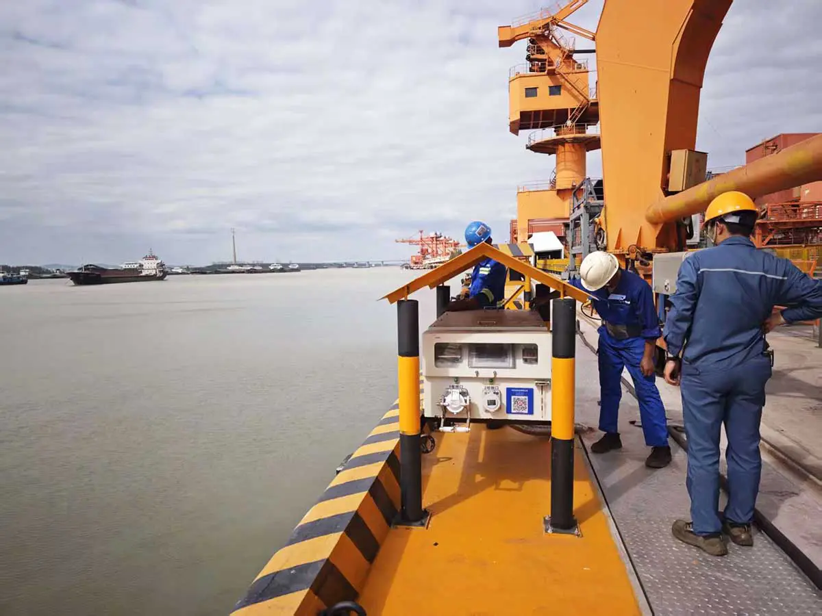
In August 2026, two 200 kVA, 400/400 V three-phase isolation transformers from Winzele were installed and commissioned at the raw-material logistics terminal of Shanghai Meishan Iron & Steel Co., Ltd., a Baosteel subsidiary. Each unit carries its own shore power path for one berth — berth 1 and berth 2 — so the terminal gained two independent 400 V isolated supplies for vessels at berth.
The scope ran from the existing low-voltage switchgear outward. Each transformer cabinet was integrated with the existing LV outgoing board using site-measured copper busbar connections, then connected by cable to a dedicated shore power control cabinet on its berth. Commissioning covered the transformer checks, the interlocked dual-outlet logic, the Internet of Things (IoT) interfaces and mobile-app start/stop control.
Project at a Glance
| Item | Project data |
| Customer | Shanghai Meishan Iron & Steel Co., Ltd. (Baosteel subsidiary) |
| Application | Isolated shore power for berthed vessels |
| Completion | August 2026 |
| Berths | Berth 1 and berth 2 |
| Isolation transformers | 2 × 200 kVA, three-phase, 400/400 V |
| Input / output voltage | 400 V / 400 V |
| Shore power control cabinets | 2, one per berth |
| Shore outlets | 250 A for larger vessels; 125 A for smaller vessels |
| Outlet interlock | Only one outlet energized at a time; alarm and output disconnect if both plugs are inserted |
| Commissioning | Energization, insulation and voltage checks; simulated connection; IoT and mobile-app tests; dual-outlet interlock test |
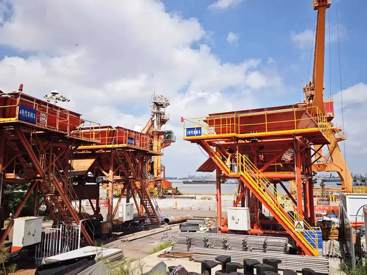
Two Independent Shore Power Paths
Each berth runs on its own circuit:
Existing LV Outgoing Switchgear
    ↓
200 kVA, 400/400 V Isolation Transformer
    ↓
Cable
    ↓
Berth-Side Shore Power Control Cabinet
    ↓
250 A or 125 A Outlet
    ↓
Vessel
Every component in that chain belongs to one berth. The transformer on berth 1 feeds berth 1, and the transformer on berth 2 feeds berth 2; nothing is paralleled between them. This is two 200 kVA systems, not one 400 kVA unit.
The identical 400 V input and output ratings are deliberate. The transformer’s job here is electrical isolation, not voltage conversion. Sitting between the plant LV network and the berth connection equipment, it creates a defined electrical boundary for each shore power circuit: the isolated secondary feeds the shore power control cabinet, its connection-detection circuitry and the selected outlet without a conductive path back through the windings to the upstream board.
The transformer is the core power component of the path. The berth-side cabinet manages everything around it — connection detection, outlet selection and the operating interlocks that keep the sequence safe. In this project the transformer cabinet, shore cabinet and control logic were commissioned as one operating chain, not as separate boxes.
Adapting the Transformer Cabinets to the Existing LV Switchgear
Installation did not stop at positioning the cabinets. The work followed the real interface of the existing switchgear:
- Cabinet placement. Each transformer cabinet was positioned as an adjacent section on the outgoing side of the existing LV board.
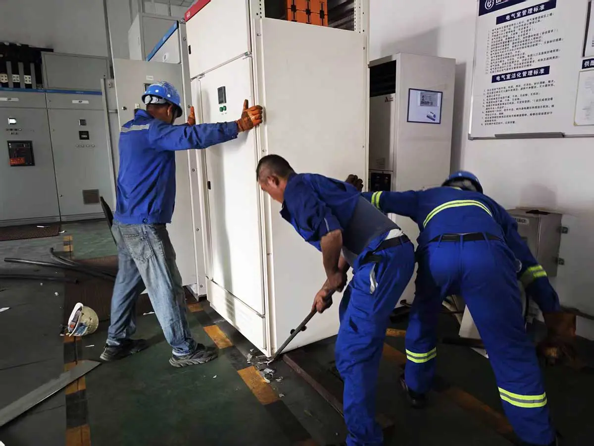
One of the transformer cabinets being positioned for integration with the existing LV outgoing switchgear. - Interface measurement. The team measured the busbar connection points on the existing cabinet before any metal was cut.
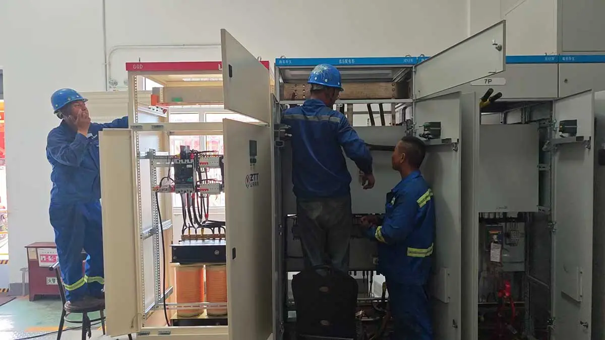
On-site measurement ensured that the new transformer cabinet connections matched the existing switchgear interface. - Copper link fabrication. Busbar pieces were made on site to match the measured dimensions.
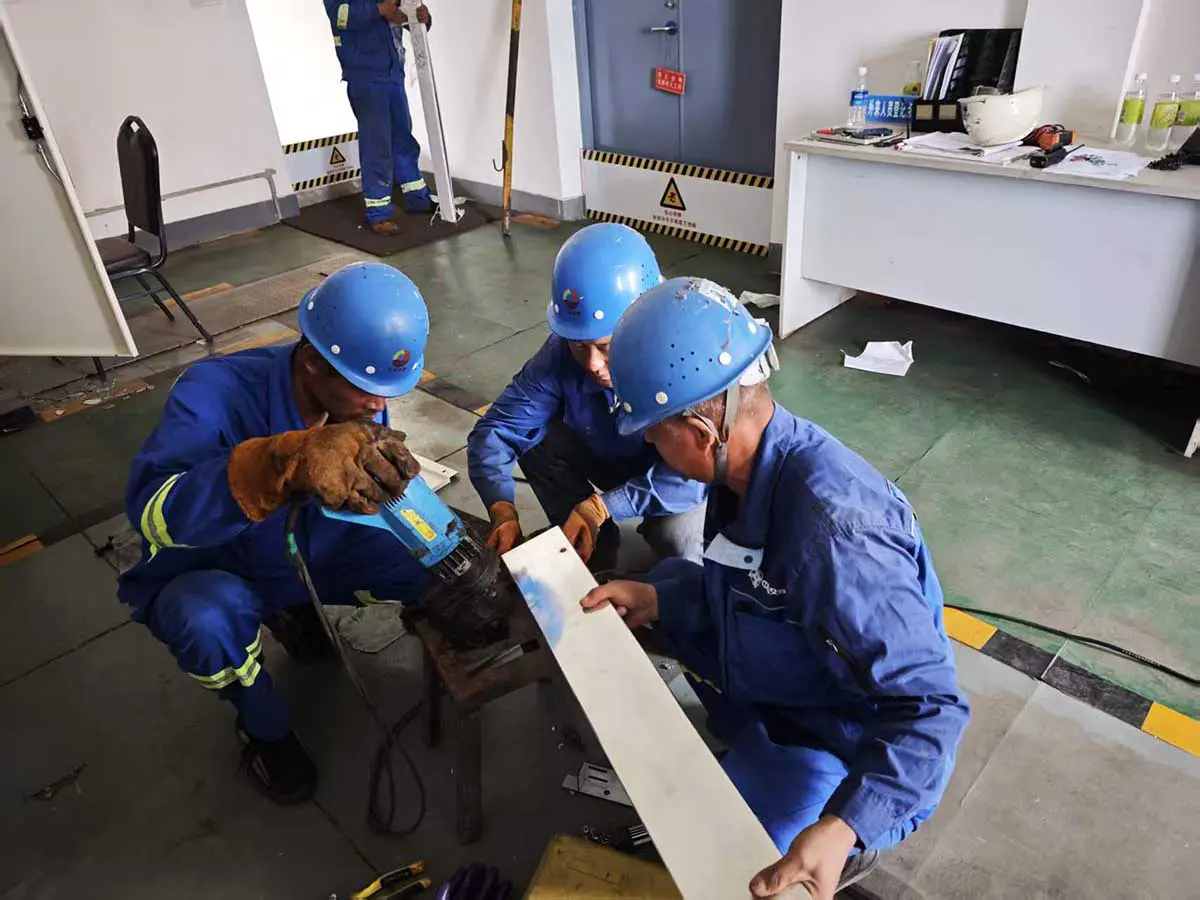
A copper busbar connection piece being fabricated on site after the interface dimensions were confirmed. - Connection. The fabricated links were fitted between the existing outgoing section and each transformer cabinet, completing the busbar work.
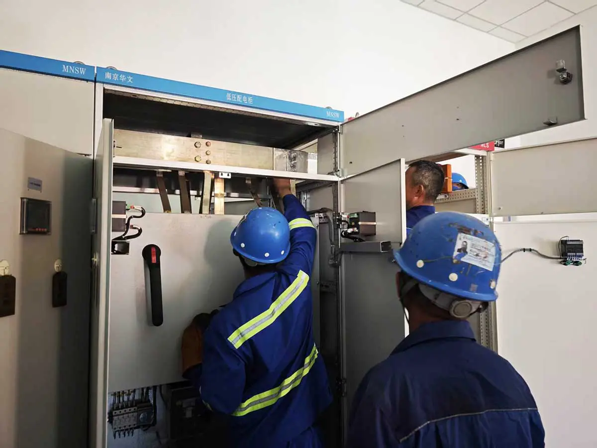
The fabricated copper connection being fitted to the existing low-voltage cabinet. - Internal checks. Connections inside each cabinet were checked before energization.
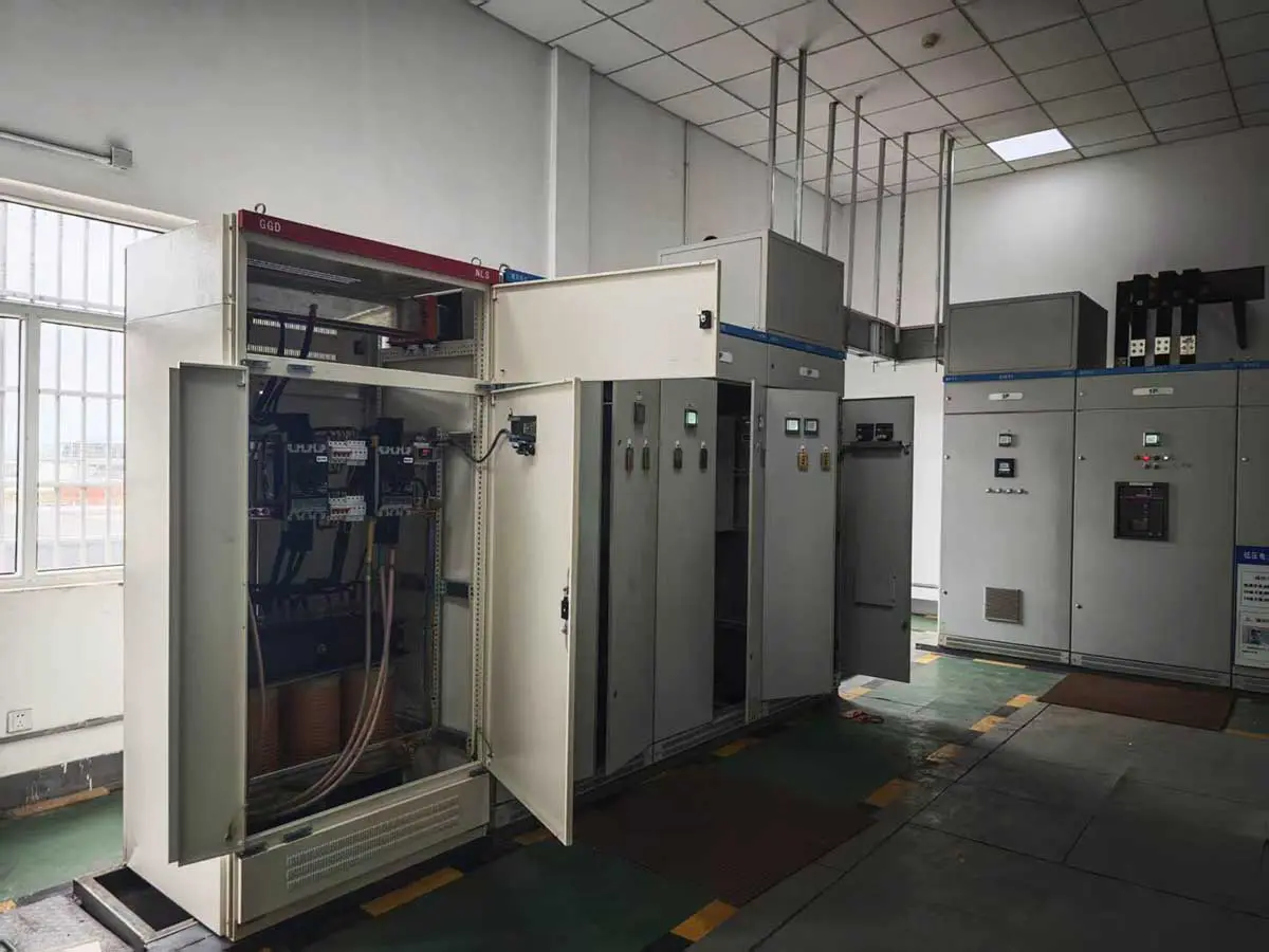
One of the 200 kVA transformer cabinets after the internal power connections were completed. - Cable to the berth. The secondary output of each transformer was then connected by cable to the shore power control cabinet at the corresponding berth.
The three busbar photographs above follow one sequence — measurement, fabrication, final connection. That sequence is the point: the cabinets were adapted to the existing board, not placed next to it. The side-by-side arrangement means physical lineup and electrical integration with the existing LV switchgear; the two transformers never share a load bus.
One Outlet for Each Vessel Connection
Each shore power control cabinet offers two outlets: a 250 A interface for larger vessels and a 125 A interface for smaller vessels. These are rated currents of the connection interfaces, and they are not two loads that can run at the same time.
The cabinet watches the connection state of both outlets. Insert both plugs and it raises an alarm and disconnects the shore power output. That interlock protects the single 200 kVA transformer serving the berth from being loaded through both interfaces at once, and it forces a clean operating sequence: connect one vessel, supply it, then release the outlet for the next call.
This was not a paper-only feature. The engineers simulated the double-connection condition during commissioning and watched the cabinet raise the alarm and drop the output as designed.
Testing the Complete Shore Power Sequence
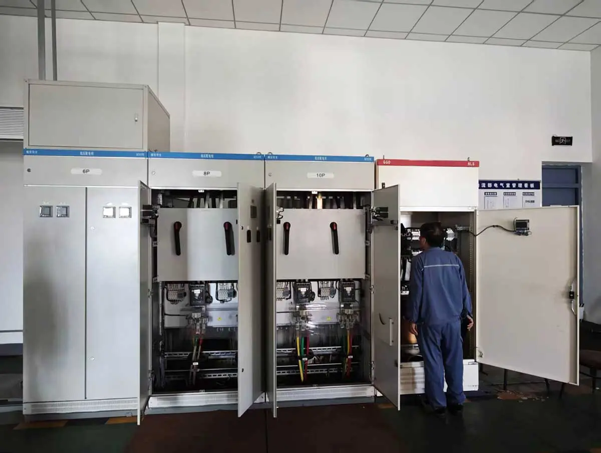
Winzele field engineers and Baosteel electrical engineers ran the commissioning together. First came the transformer work: pre-energization inspection, insulation checks and input/output voltage measurement at each cabinet. The IoT interfaces were commissioned together with the mobile-app start and stop control functions.
During commissioning, the team temporarily bridged the P1–P2 connection-detection contacts to simulate a vessel connection. This is a control and interlock test — the main power circuit stays untouched. With one simulated connection in place, they started and stopped the shore power output from the mobile app. Then they simulated both outlets being connected at the same time; the cabinet raised the alarm and disconnected the output, confirming the mutually exclusive outlet logic under the abnormal condition.
International Direction and IEC Context
Shore power is moving from optional equipment to planned infrastructure. In the European Union, the Alternative Fuels Infrastructure Regulation (AFIR) requires qualifying maritime ports on the trans-European transport network to provide shore-side electricity covering at least 90% of relevant calls by large container and passenger ships by the end of 2029. FuelEU Maritime then requires covered container and passenger ships above 5,000 gross tonnes to use onshore power or another zero-emission technology at berth in AFIR-covered ports from January 1, 2030, extending to other EU ports where shore power is available from 2035. AFIR — Regulation (EU) 2023/1804 · European Commission — FuelEU Maritime
The United States combines federal investment with state and port-level rules rather than one national timeline. California’s Ocean-Going Vessels At Berth Regulation expanded requirements to container, refrigerated-cargo and cruise vessels in 2023, added roll-on/roll-off and tanker vessels at Los Angeles and Long Beach in 2025, and schedules tanker coverage at other California ports for 2027. At federal level, the U.S. Environmental Protection Agency awarded 51 grants worth nearly USD 3 billion through the Clean Ports Program, with shore power among the eligible port infrastructure. California Air Resources Board — At-Berth Regulation · U.S. EPA — Clean Ports Program
The current international reference for low-voltage shore connections is IEC/IEEE 80005-3:2025, which covers three-phase systems rated 250 A and above at 400 V AC to 1,000 V AC. IEC — IEC/IEEE 80005-3:2025 For this project, the 400 V, 250 A outlet matches that published electrical rating range. However, the standard excludes inland navigation vessels, and the vessel class served by this terminal is not documented in this case. The 125 A outlet is also below the standard’s 250 A threshold. These values are therefore included as international engineering context only and do not establish that the project falls within the standard’s scope or conforms to it. IEC 60309-5 separately defines the dimensional compatibility of the dedicated low-voltage shore connection plug-and-socket family used with these systems. IEC — IEC 60309-5:2017
The standards are provided as international design context; this case study does not claim IEC certification or formal conformity for the project.
Project Outcome
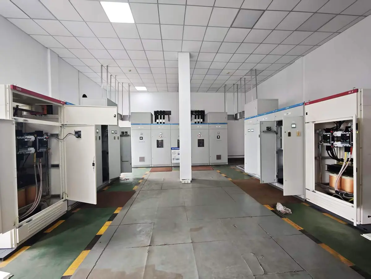
By the end of commissioning, berth 1 and berth 2 each had an independent 400 V isolated shore power path. Transformer energization, insulation, input and output voltage, shore cabinet communication, mobile-app operation, connection detection and dual-outlet interlocking had all been verified as one system.
The project shows how a shore power isolation transformer fits into an existing industrial LV network: measure the real interface, fabricate the busbar work, connect the transformer into the board, then hand the isolated output to a berth-side cabinet that manages the vessel connection. This case provides a practical example of integrating shore power isolation transformers with existing industrial low-voltage switchgear and berth-side connection controls.


