

1500kW 380V to 200V Transformer System for Semiconductor Manufacturing Equipment
Industrial technical case study — customized transformer voltage conversion system for imported semiconductor manufacturing equipment.
Semiconductor manufacturing equipment requires highly compatible power systems. Production tools used in wafer processing, packaging and thin-film deposition are engineered around specific electrical standards, and many imported machines are designed for a 200V three-phase supply. The factory site in this project operates on a 380V three-phase industrial network. Because the 200V-rated equipment cannot be connected directly to the 380V supply, the voltage mismatch had to be resolved before the imported tools could be commissioned.
Winzele designed and manufactured a customized three-phase dry-type isolation transformer system for this application: a 1500kW power conversion solution built on an 1800kVA transformer, converting 380V three-phase input to 200V three-phase output. The scope covered transformer design, vacuum pressure impregnation insulation treatment, internal copper busbar configuration, switchgear integration, factory testing and on-site commissioning, delivering a complete industrial power conversion solution for the semiconductor production line.
1. Project Overview
In 2025, the company integrated a new power conversion system for its semiconductor manufacturing facility. The facility operates a wide range of imported production equipment, including evaporation systems, automatic wafer thinning machines, packaging and polishing equipment, automatic film mounting machines, bonding machines and debonding machines. These tools were originally built for a 200V three-phase power standard, while the factory’s incoming industrial supply is 380V three-phase.
| Customer | Shanghai Welnew Micro-Electronics Co., Ltd. |
| Industry | Semiconductor Manufacturing |
| Application | Power conversion for imported semiconductor equipment |
| Installed Equipment | 1500kW power conversion system with 1800kVA three-phase dry-type isolation transformer |
| Input Voltage | 380V three-phase |
| Output Voltage | 200V three-phase |
| Solution | Customized isolation transformer voltage conversion system |
The system was specified, manufactured and delivered as a complete power package: the transformer, its internal connections, the output distribution and the system cabinets were designed as one integrated assembly, so the facility received a ready-to-connect power conversion unit rather than a loose collection of components.
The project ran through 2025, starting with a load survey of the connected equipment, followed by transformer specification, factory production and testing, delivery and on-site commissioning. The equipment list covers evaporation systems for thin-film deposition, automatic wafer thinning machines for backside grinding, packaging and polishing equipment, automatic film mounting machines, bonding machines and debonding machines used in the assembly line. Together these tools represent a continuous production load that requires a dedicated power conversion stage between the facility supply and the tool power distribution.
2. Power Challenge
The core challenge in this project was not voltage stability — it was voltage compatibility. The equipment and the site were not designed for the same electrical standard.
- Imported semiconductor equipment requires 200V three-phase power. The production tools installed at this facility were designed and manufactured for a 200V three-phase power system, and their motors, heaters, control circuits and safety interlocks are all specified around this voltage level.
- The factory supply is 380V three-phase. The on-site industrial network delivers 380V, roughly 90% above the equipment’s design voltage. Connecting the tools directly to this supply would exceed their voltage tolerance and could damage drives, control boards and insulation.
- A voltage conversion stage is required. Feeding 380V into 200V-rated equipment is not feasible, so the voltage mismatch had to be resolved at the power distribution level before the imported tools could be commissioned.
A 380V to 200V transformer is therefore an essential part of the semiconductor equipment power supply chain. The conversion stage had to provide stable three-phase output for the connected tools within the space, cooling and safety constraints of the production building, while preserving the 50Hz frequency of the facility network.
3. Transformer Solution
Winzele supplied a customized three-phase transformer system with the following power flow:
380V three-phase input
↓
Three-phase dry-type isolation transformer
↓
200V three-phase output
↓
Imported semiconductor manufacturing equipment
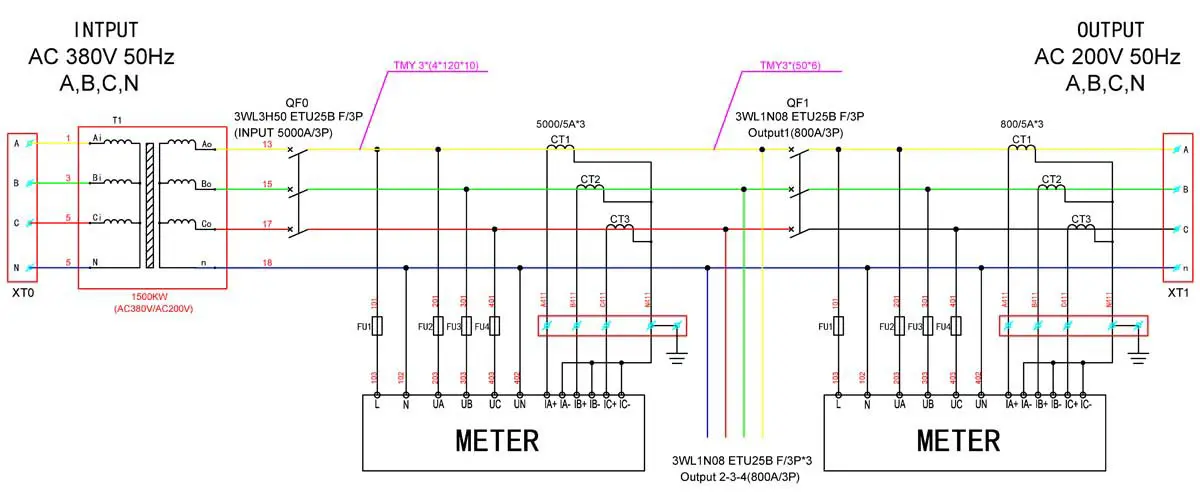
380V to 200V transformer system configuration for semiconductor equipment power conversion
System capacity selection. The system power rating of 1500kW was selected according to the connected equipment load requirements, covering the simultaneous operation of the production tools with their rated margins. The transformer itself was rated at 1800kVA, which is the apparent power that the transformer can deliver continuously. The two figures describe different quantities: 1500kW refers to the active power consumed by the equipment, while 1800kVA refers to the transformer’s rated apparent power, which accounts for the power factor of the load. Sizing the transformer above the pure active-power demand provides the reactive power headroom and thermal margin needed for stable operation under real production loads.
Three-phase transformer design. The unit is a three-phase dry-type isolation transformer designed specifically for this voltage conversion duty. The core and winding configuration was engineered for the 380V to 200V transformation ratio, with separated primary and secondary windings arranged to deliver balanced three-phase output. The transformer structure is compact and integrated with its enclosure, so it occupies a single cabinet footprint instead of a separate transformer room.
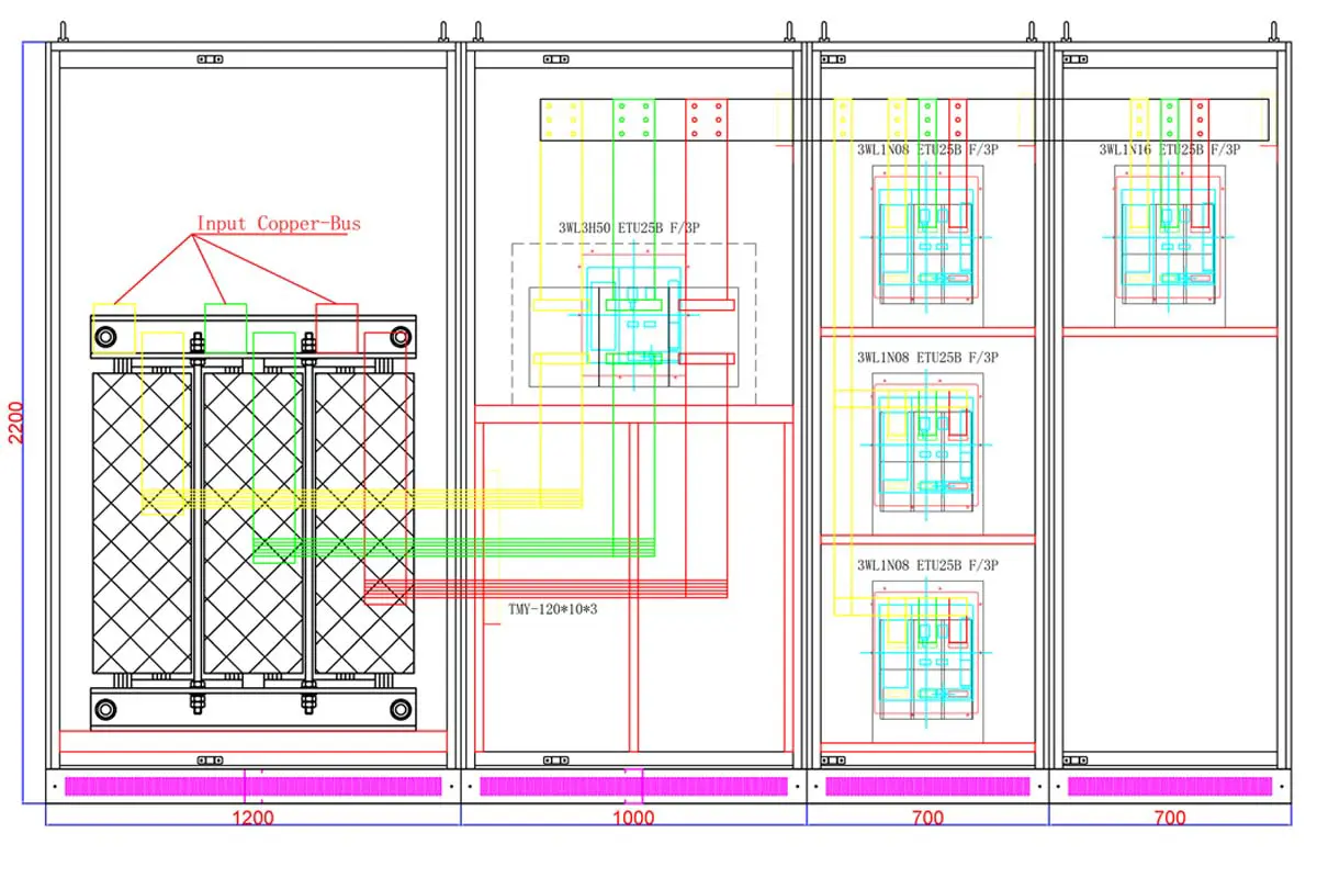
Customized three-phase transformer design for semiconductor manufacturing application
Copper conductor and busbar design. The transformer windings use copper conductors sized for the rated current of the system. Internally, the secondary-side connections are arranged with copper busbars that carry the output current between the transformer and the outgoing terminals.
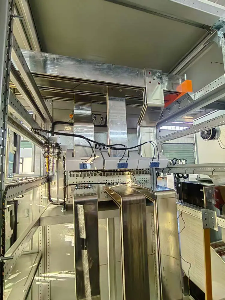
Internal copper busbar configuration of the transformer system
The busbar layout keeps connection points to a minimum, which reduces joint resistance and local heating under continuous production load. Because semiconductor tools can draw high inrush currents when powered up, the conductor cross-sections were checked against both steady-state current and short-time overload conditions.
The connected load profile also influenced the design. Semiconductor tools contain variable-speed drives, heating elements and control electronics, so the output side of the transformer must supply both steady production current and short-duration starting peaks. The transformer was designed with the impedance and regulation characteristics needed to keep the output voltage within the equipment’s operating band during load changes, while the copper busbar and terminal arrangement was sized for continuous duty at the rated output current.
Electrical isolation. As an isolation transformer, the unit provides galvanic separation between the factory supply and the semiconductor equipment loads. This separation prevents the propagation of neutral currents and common-mode disturbances between the two systems, which matters in a production environment where sensitive controls and measurement circuits share the same power network.
Customized enclosure and integration. The transformer was built into a customized enclosure with the output cabinet included in the same assembly. The enclosure provides mechanical protection and touch-safe construction, while the integrated switchgear allows the output to be controlled, monitored and disconnected locally during maintenance.
4. Manufacturing and Quality Control
The transformer was manufactured in the Winzele factory under controlled production steps. Every stage of the manufacturing process was documented, and each unit was subjected to electrical testing before shipment.
As a custom transformer manufacturer, Winzele designs and manufactures transformer systems according to equipment voltage requirements, installation conditions and industrial application environments. For this project, the production sequence covered winding, insulation treatment, assembly and the complete electrical test program described below.
Winding inspection. After winding, the transformer coils were checked for correct turns count, connection polarity and DC resistance balance between phases. Winding resistance values were recorded and compared against the design specification.
Insulation treatment. The wound assemblies were processed through vacuum pressure impregnation (VPI). In this process, the windings are placed in a vacuum chamber, air and moisture are removed from the insulation structure, and insulating varnish is drawn into the winding under vacuum and pressure. The impregnated insulation improves dielectric strength, mechanical rigidity and thermal conductivity of the coil assembly.
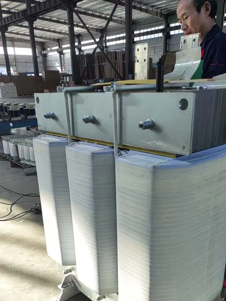
Transformer manufacturing process during production |
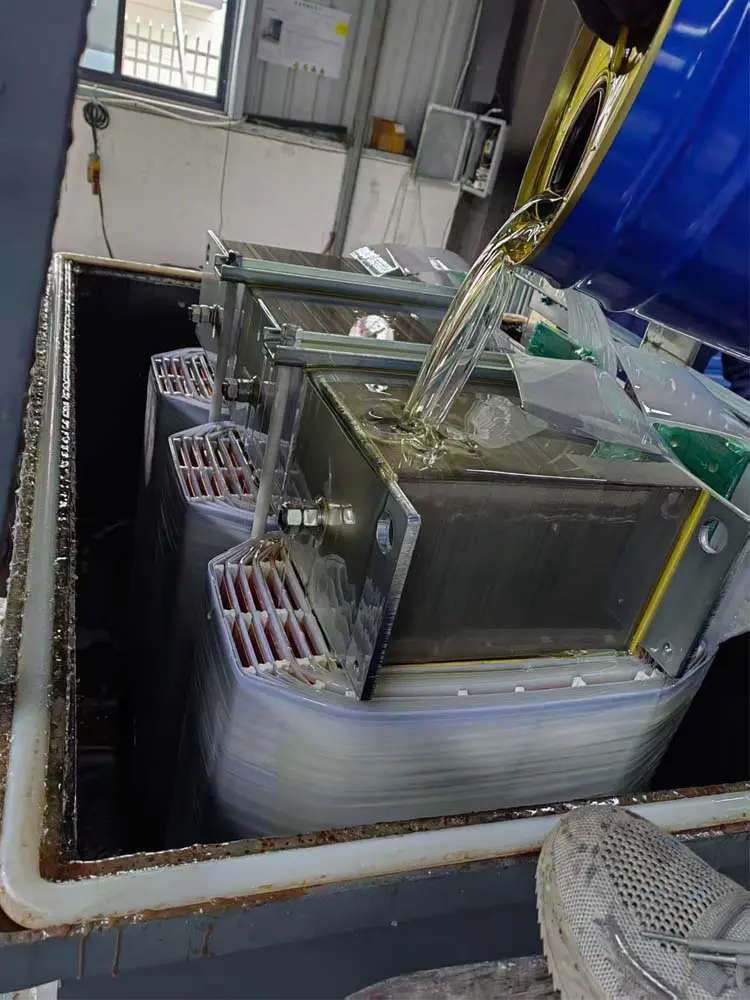
Transformer vacuum pressure impregnation process to improve insulation reliability |
Electrical parameter testing. The completed transformer underwent electrical parameter verification, including turns ratio, no-load current and no-load loss measurement, to confirm that the voltage conversion characteristics matched the 380V to 200V design target.
Withstand voltage testing. Insulation strength was verified by applying the specified test voltage between windings and between windings and ground. The test confirms that the insulation system can withstand the electrical stress of normal operation plus the expected transient conditions.
Load testing. The transformer was load-tested to evaluate temperature rise and output performance under rated conditions. Temperature readings were taken during the test to confirm that the cooling design keeps the winding temperature within the insulation class limit.
The winding insulation system was selected for dry-type operation, and the VPI-treated coils were cured under controlled temperature to stabilize the impregnated varnish. Insulation class and temperature rise were specified so the transformer can operate continuously at the rated load in the ambient conditions of the electrical room. Each production step was recorded with inspection sign-off, and the test results were compiled into the delivery documentation together with the electrical drawings.
System commissioning at the factory. The transformer, switchgear and output connections were assembled and commissioned together before shipment. The complete system was energized and checked as one unit, so the factory test covered not only the transformer alone but the integrated transformer-and-switchgear assembly delivered to the site.
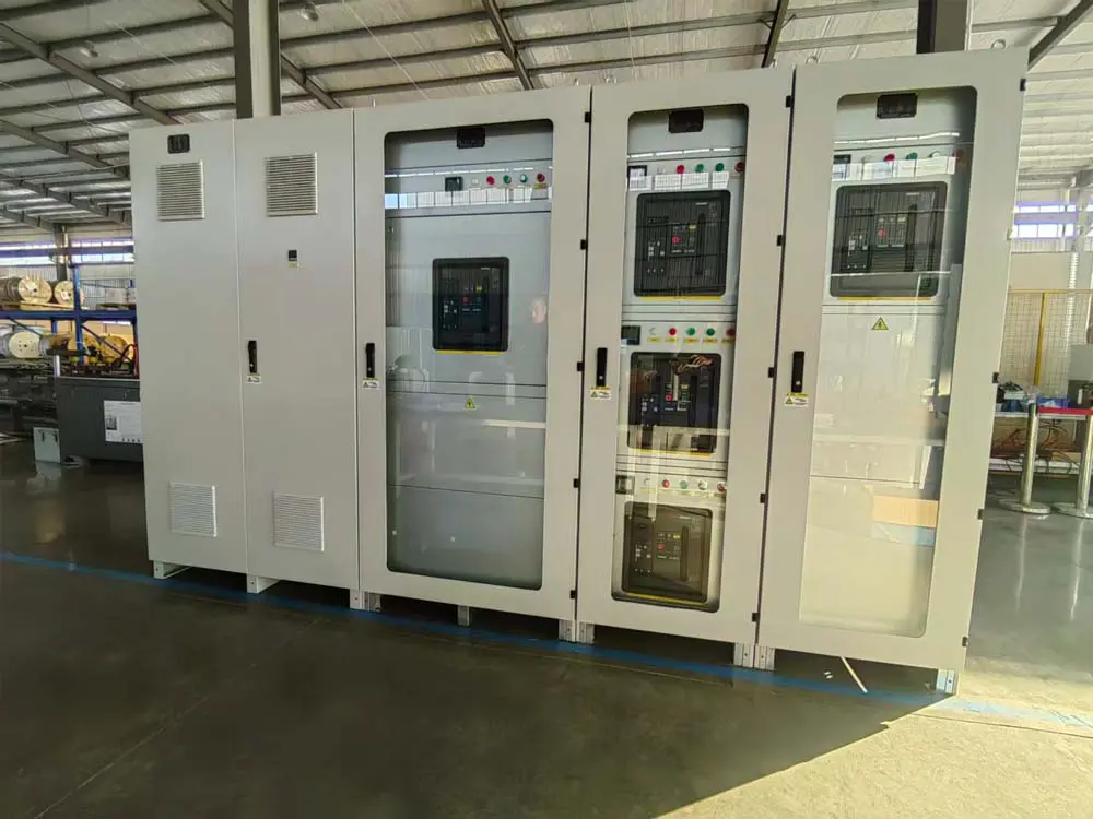
Transformer and switchgear system commissioning before shipment
5. Installation and Commissioning
The system was delivered to the semiconductor manufacturing facility and installed on site by the project team.
Transformer cabinet installation. The transformer cabinet was positioned at the prepared location in the electrical room, close to the incoming 380V supply point. The cabinet footprint had been confirmed during the design phase, so the installation was a direct placement with the incoming cable connection made to the primary side.
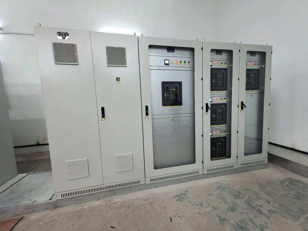
Completed transformer cabinet installation at semiconductor manufacturing facility
Output cabinet connection. The output cabinet was connected to the transformer secondary side and to the distribution circuits feeding the imported equipment. The internal copper busbar assembly provided the high-current path between the transformer output and the outgoing breakers.
System commissioning. After mechanical and electrical installation, the complete system was energized and commissioned. Input voltage, output voltage and phase balance were measured and verified against the 380V in / 200V out design specification. Protection settings and control functions were checked with the equipment side disconnected first, then the connected tools were powered up in sequence.
The site work was coordinated to minimize disruption to the production area. Cable routing between the incoming supply, the transformer cabinet and the output cabinet was planned during the design stage, and the final connections were terminated and torqued according to the installation instructions before the energization sequence.
The completed transformer system was integrated into the semiconductor manufacturing facility and provided the required 200V power supply for the imported equipment.
6. Project Result
The project delivered the intended outcome without changing the factory’s incoming supply infrastructure:
- Solved the voltage compatibility issue. The 380V to 200V transformer system converted the factory supply to the voltage level required by the imported semiconductor equipment, eliminating the voltage mismatch at the source.
- Enabled imported semiconductor equipment operation. With a stable 200V three-phase supply available, the evaporation systems, wafer thinning machines, packaging and polishing equipment, film mounting machines and bonding equipment could be operated on the existing 380V facility network.
- Improved power system integration. By combining the transformer, copper busbar connections and switchgear into one customized assembly, the installation reduced the number of separate components and connection points compared with a staged conversion approach.
- Provided a customized industrial power solution. The system was designed around the specific load profile of the facility, with capacity, enclosure and output configuration matched to the actual production equipment.
The project demonstrates a practical approach to a common problem in semiconductor manufacturing: adapting imported equipment to the local power standard with a purpose-built transformer system. Since commissioning, the system has operated as the dedicated power conversion stage for the imported production tools, with the transformer and switchgear integrated into the facility’s electrical infrastructure.
7. Related Solution
- Industrial Transformer Solutions — three-phase and isolation transformers for industrial power applications
- Three-Phase Dry-Type Isolation Transformer — dry-type isolation transformer for industrial voltage conversion
- Voltage Conversion Solutions — customized input/output voltage configurations for equipment power supply
Semiconductor manufacturing equipment power conversion project — 2025.


