Reactive Power Capacitor Compensation-3(Local reactive power compensation)
Local Capacitor Compensation for Motor Circuits
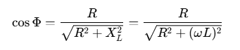
In practical power systems, the equivalent circuit of most electrical equipment (including induction motors) can be regarded as a series circuit of resistance and inductance . Its power factor is:
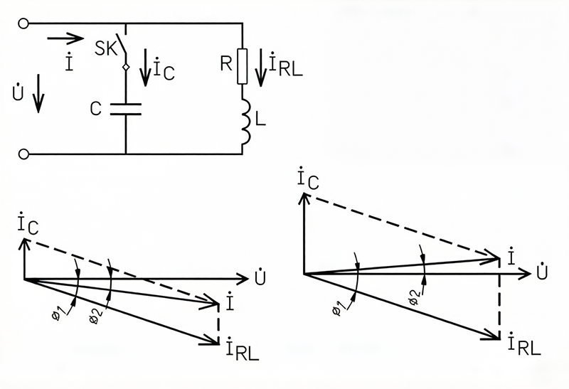
When a capacitor is connected in parallel to the circuit, the current equation becomes:
![]()
Figure 3 shows the phasor diagram of compensation.
Figure 3 Under-compensation and Over-compensation
-
In the left phasor diagram (under-compensation), the current vector lags behind the voltage phasor.
-
In the right phasor diagram (over-compensation), the current vector leads the voltage phasor.
Over-compensation is generally undesirable because it can cause an increase in the secondary voltage of the transformer. Moreover, capacitive reactive power also leads to energy losses and increases the temperature rise and loss of the capacitor, thereby affecting its service life.
Table 1 provides the recommended capacitor capacity for improving the power factor of motor loads:
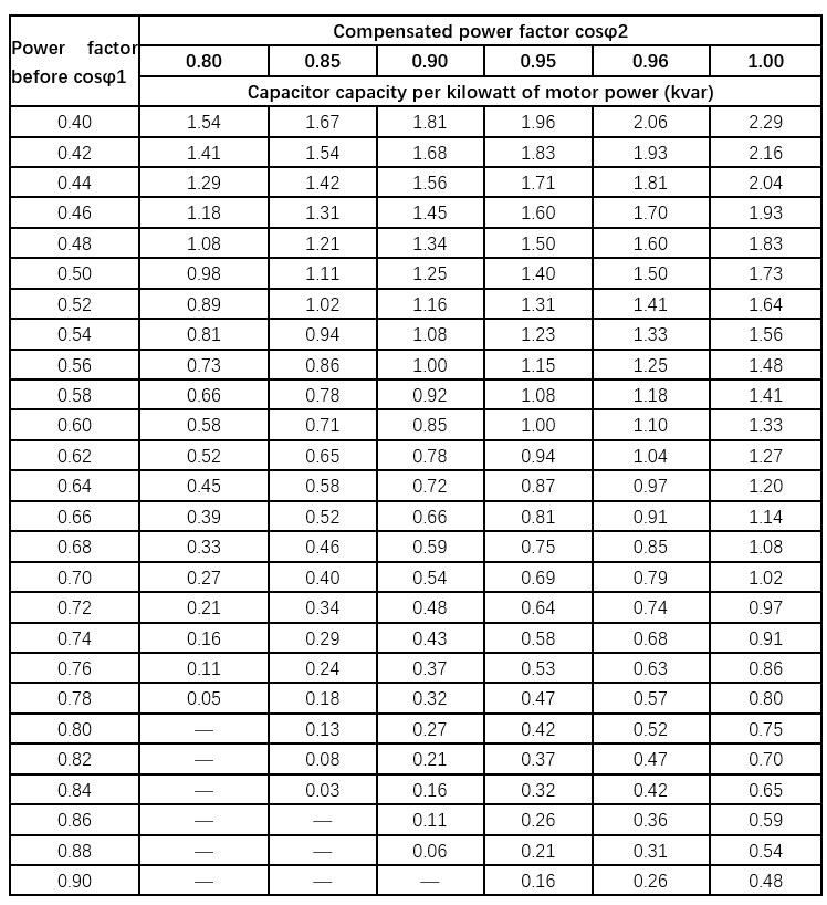
Instructions for Using the Table:
-
General Compensation Scenario: For a motor load with a typical power factor of 0.7, if it needs to be compensated to 0.9, the table yields a compensation factor of 0.586 kvar/kW. For an active power of 100 kW, the total required compensation capacitor capacity is: 100 kW × 0.586 kvar/kW = 58.6 kvar.
-
Critical Limitation: For three-phase AC induction motors, the compensation power must not exceed 90% of the motor’s no-load reactive power. This is to prevent overvoltage that may occur due to over-compensation when the motor is shut down.
-
Simplified Calculation Formula: The compensation capacitor for motor loads can also be approximately estimated using the following simplified formula:
where
is the rated power of the motor.
Qc is the capacitance of the compensation capacitor.