Reactive Power Capacitor Compensation-1(Load calculation method)
The electrical load calculation method is applicable to determining the reactive power compensation capacitor capacity in the main distribution room.
This method applies to the total load power of an enterprise or institution. The rated power is multiplied by a demand factor to obtain the calculated active power Pj of the load. Then, the calculated reactive power Qj, calculated apparent power Sj, and calculated current Ij are derived.
We sum the load’s Pj, Qj, Sj, and Ij, and multiply by a simultaneity factor to obtain the calculation parameters for the workshop or floor distribution room.
Next, we sum the Pj, Qj, Sj, and Ij of each workshop or floor distribution room, and multiply by a simultaneity factor (generally taken as 0.85) to obtain the calculation parameters for the main distribution room.
Since the total load capacity of a power transformer generally accounts for 70% of its rated capacity, we divide Sj by 0.7, taking the larger value to obtain the power transformer capacity Sn. Simultaneously, we use Qj to obtain the reactive power compensation capacity.
We ensure the rated current of the low-voltage main incoming circuit breaker is greater than Ij. Combining this with the transformer’s capacity Sn, rated voltage Un, and impedance voltage Uk%, we can calculate the transformer’s short-circuit current Ik, and thus determine the circuit breaker’s ultimate short-circuit breaking capacity Icu.
The reactive power compensation capacitor capacity is, of course, Qj.
Additionally, if the low-voltage primary distribution system switchgear directly connected to the power transformer only has feeder circuits and no motor control circuits, the reactive power compensation circuit capacity is approximately 0.3 to 0.35 times the transformer capacity.
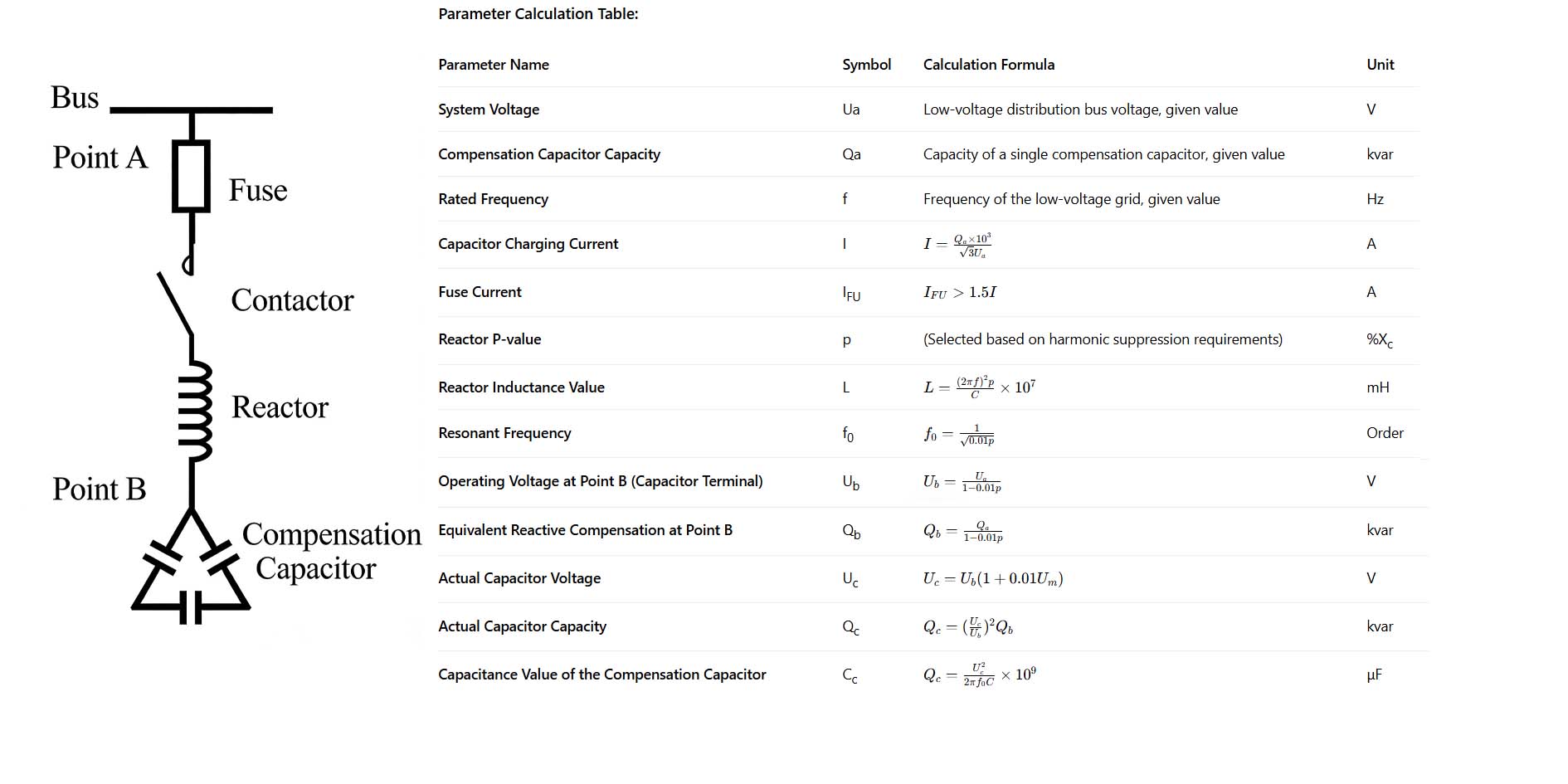
Low-voltage reactive power compensation capacitor related parameter calculation table