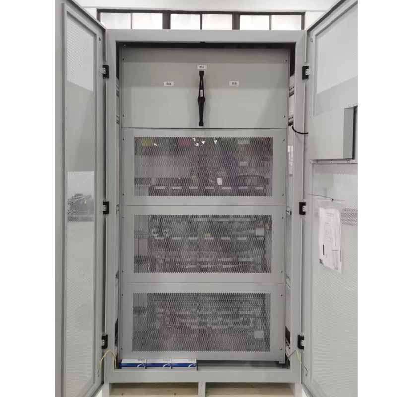
Static Non-contact SCR Voltage Regulator
Rated Power: 3~3000KVA
Input Voltage: Customizable
Input Frequency: 50/60Hz±10%
Output Voltage: Customizable
MOQ: 1 Set/Piece
Brand: WINZPOWER
Product Introduction
ZDBW/ZSBW MCU(Microcontroller Unit) control intelligent static no-contact SCR single/three-phase AC voltage stabilizer series is newly designed big power AC voltage stabilizer for the global market. Its basic techenology came from the updated international AC stabilizer field.
Working principle
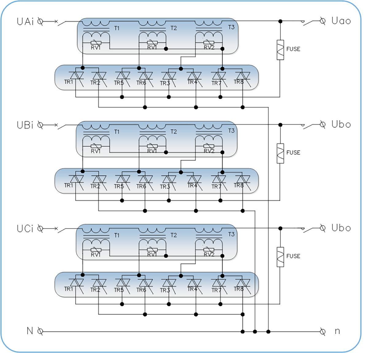
This series products based on the advanced power electron technology and digital fuzzy control technology, abandoned the ordinary voltage regulator’s carbon brush and mechanical structure, gathered the advanced combination winding compensation technology, no-contact switch technology and MCU control AC voltage stabilizer technology in one body. When a fluctuating voltage is detected, MCU controls the ON and OFF of the power devices to change the compensation voltage amount and phase to keep the voltage in stable.This series products have reliable voltage stabilize function and fast instant responce function ( responce time ≤20ms); have the characteristics of high precision, no spark, no contact, without mechanical transmission, maintenance-free, interference rejection, long life, high efficient and energy saving, fast regulation, auto three-phase balance, and fault diagnosis function. At the same time, this series products have time delay, over/under voltage alarm, protection functions.
Voltage regulation principle
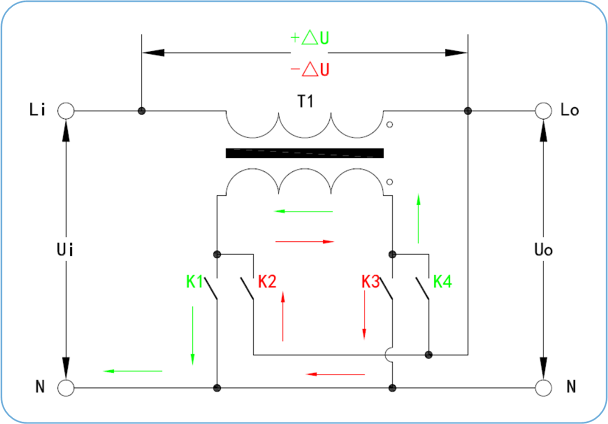
Take the compensation transformer T1 as an example to illustrate the specific voltage regulation principle:
When the compound switches K1 and K4 are turned on, the secondary voltage of the compensation transformer T1 is in the same polarity as the power supply voltage, and is positively superimposed with the power supply voltage, which increases the output voltage Uo;
The input-output voltage relationship is: Uo=Ui+△U
The green shear indicates that the current flows from L to N, and the system performs positive superposition compensation (increases the voltage).
When the compound switches K2 and K3 are turned on, the secondary voltage of the compensation transformer T1 is in the opposite polarity to the power supply voltage, and is reversely superimposed with the power supply voltage, which reduces the output voltage Uo;
The input-output voltage relationship is: Uo=Ui-△U
The red shear indicates that the current flows from L to N, and the system performs reverse superposition compensation (reduced voltage).
Among them, the increase or decrease of the output voltage Uo depends on the ratio design of the compensation transformer, and the number of compensation transformers in the compensation transformer group and the ratio of each compensation transformer are determined according to the maximum adjustment voltage capacity range and the minimum adjustment voltage level.
Control Principle Diagram
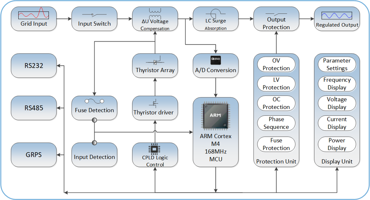
Control principle topology diagram
List Of ZSBW Static AVR Technical Parameters
| Input Technical Parameters | ||
| Item | Technical Indicators | Remark |
| Rated Voltage(Vac) | Three Phase 200V 208V 220V 380V 400V 440V 480V(Any voltage can be customized)Single phase 110V 220V 230V 380V(Any voltage can be customized) | Three phase three wire (L1, L2, L3) Ground(PE).Single phase two line (L, N) Ground(PE).The system can use a Neutral line or not.Any line entry method can be customized |
| Input Voltage Range(%) | (Rated Voltage)±20%.e.g.380V±20%(Customizable other voltage input ranges) | Generally, the input voltage range can be ±15% 20% 30% 40% of the rated voltage. |
| Input Frequency(Hz) | Default 40~79Hz | Other frequencies can be customized |
| Efficiency | 98% | |
| Output isolation transformer | △/Y or Y/Y | Optional |
| Output Technical Parameters | ||
| Voltage Regulation Mode | Thyristor adjustment transformer | |
| Output voltage(Vac) | Three-phase 380V/400V (±10% adjustable) Single-phase 220V/230V (±10% adjustable) |
Other voltages can also be customized, e.g: Three-phase 200V 220 440V 480V or other. |
| Output voltage stability (average accuracy) | ±1-5% (2-5% for normal products) | |
| Dynamic Response time | 20~40ms(Relative AC input voltage) | |
| Output THD Increase | <0.1%(static and dynamic) | No additional waveform distortion (static and dynamic) is generated. The voltage THD increment is less than 0.1% |
| Output Frequency | Same as input frequency | |
| Three-phase imbalance | Three-phase voltage automatic control balance | |
| Applicable load type | Any load type (resistive, inductive, capacitive) | |
| Overload capacity | 120% 10min 140% 1min | |
| Bypass function | Automatic bypass when an internal fault occurs | Manual bypass optional |
| Controller parameters | ||
| Control Mode | Full digital control | The analog part is used for input and output signal conditioning |
| Main control unit | The main chip uses STM32F4XX for control and measurement | Some models use ARM master control with DSP function |
| Control strategy | 8421 encoding | |
| SCR Drive Mode | Pulse transformer zero-crossing trigger | |
| Voltage Compensation time | 100ms | Load power 0-100% |
| Voltage and current measurement methods | True RMS sampling (three-phase synchronization) | RMS & FFT sampling 256 points |
| Voltage & Current Control Strategy | PID double closed loop control | |
| Communication interface | RS485/232/MODBUS-RTU Protocol | Optional TCP/IP, GPRS and other interfaces |
| Display parameters | ||
| Display Media | Industrial touch screen(7″or 10″) | Other sizes of LCD can also be customized |
| Display electrical parameters |
Input three-phase voltage and frequency; Output three-phase line voltage and frequency; Output line voltage average value; Output power factor;Output three-phase current; Output active power and apparent power; |
|
| Display alarm information | Input overvoltage (OV), overcurrent (OC); input undervoltage (UV); Fuse failure; Overload;Phase sequence fault; and other fault information | |
| Display accuracy | The accuracy is Class 0.5s | |
| Voltage display resolution | 0.1V | |
| Current display resolution | 0.1A | |
| Protection | ||
| Protection List | Input overvoltage (OV), overcurrent (OC); input undervoltage (UV); IGBT failure; heat sink overheat; transformer overheat; and Short Circuit. | |
| Protection Action | Cut off output and alarm;Automatic bypass;Automatically start after failure recovery | Fault dry contacts can be configured(NC&NO) |
| The Environment | ||
| Working Temperature(℃) | -35℃+55℃ | Extreme temperature environments require special customization or derating |
| Relative Humidity(RH) | 10%-90%(20℃±5℃) | |
| Altitude | <2000m | For every 1000m increase in altitude, the rating should be derated by 10%. |
| IP Class | IP20 | Other IP Classes such as outdoor IP33 can be customized |
| Other special requirements can be communicated with winzele | ||
List of ZSBW Static AVR Models & Products
1.Three-phase Model List
| Type |
Capacity (kVA) |
Current (A) |
Dimension W×D×H(mm) |
| ZSBW-20KVA | 20 | 30 | 350*600*750(Locking Castor Wheel) |
| ZSBW-30KVA | 30 | 45.6 | |
| ZSBW-50KVA | 50 | 76 | 390*650*870mm(Locking Castor Wheel) |
| ZSBW-80KVA | 80 | 121.6 | 460*700*1200mm |
| ZSBW-100KVA | 100 | 152 | |
| ZSBW-120KVA | 120 | 182 | |
| ZSBW-150KVA | 150 | 228 | 760*660*1600mm |
| ZSBW-180KVA | 180 | 274 | |
| ZSBW-200KVA | 200 | 304 | |
| ZSBW-250KVA | 250 | 380 | |
| ZSBW-300KVA | 300 | 456 | 1150*850*2000mm |
| ZSBW-350KVA | 350 | 532 | |
| ZSBW-400KVA | 400 | 608 | |
| ZSBW-500KVA | 500 | 760 | 1200*950*2200mm |
| ZSBW-600KVA | 600 | 912 | |
| ZSBW-800KVA | 800 | 1216 | 1500*1000*2200mm |
| ZSBW-1000KVA | 1000 | 1520 | |
| ZSBW-1200KVA | 1200 | 1824 | |
| ZSBW-1500KVA | 1500 | 2280 | 1600*1000*2200mm |
| ZSBW-2000KVA | 2000 | 3040 | 2000*1100*2200mm |
| ZSBW-2500KVA | 2500 | 3800 | |
| ZSBW-3000KVA | 3000 | 4560 | 2400*1200*2200mm |
2.Single-phase Model List
| Type |
Capacity (kVA) |
Current (A) |
Dimension W×D×H(mm) |
| ZDBW-3KVA | 3 | 13.6 | 220*500*370mm |
| ZDBW-5KVA | 5 | 22.7 | 260*600*400mm |
| ZDBW-10KVA | 10 | 45.5 | 350*600*400mm |
| ZDBW-15KVA | 15 | 68 | |
| ZDBW-20KVA | 20 | 91 | 390*650*670mm |
| ZDBW-30KVA | 30 | 136 | |
| ZDBW-50KVA | 50 | 227 | 390*650*870mm |
| ZDBW-60KVA | 60 | 272 | |
| ZDBW-80KVA | 80 | 363 | 460*700*1200mm |
| ZDBW-100KVA | 100 | 456 |
Application
When the devices are running at a transient state, the conjugate current and over voltage caused by the no-contact switch may destroy the device. This series products have solved this systematic problem, thus enhanced the instant overload ability, and increased system running reliability greatly. The friendly LCD display facilitates user’s operating and inquiry.
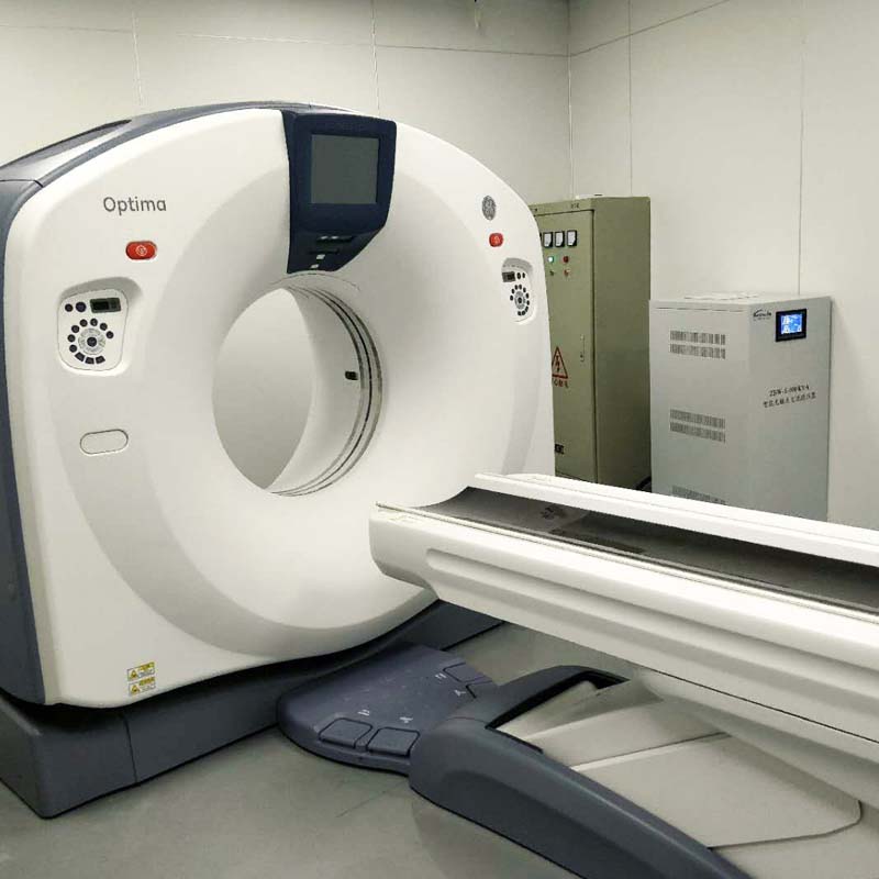
This series products mainly apply to various digital control machining center, medical equipment, printing machine, environmental testing equipment, electronic detect equipment, communication equipment, etc. Especially apply to the cruel power supply conditions such as big voltage fluctuations, voltage sudden changes, etc.
Cases and Gallery
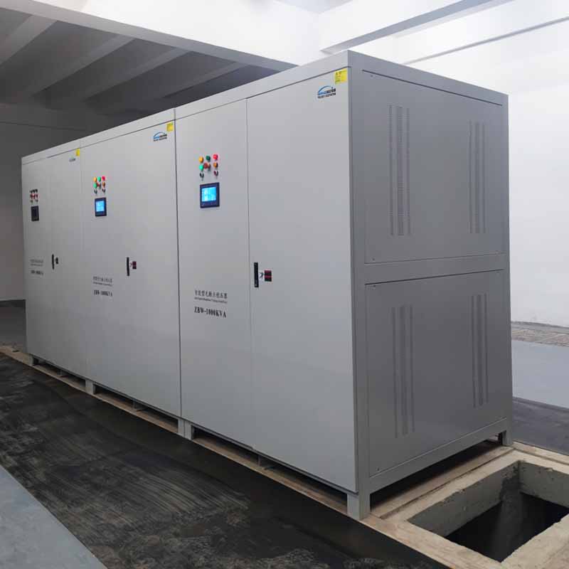
3phase-1000KVA(input 380V±20% Output 380V±2%)
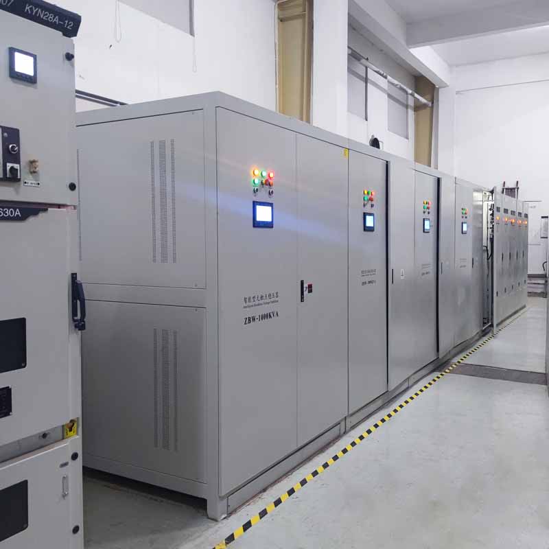
…
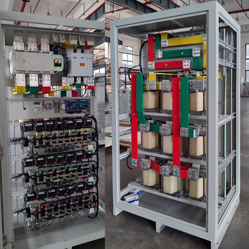
Inside(front&back)
3phase-1200KVA(input 380V±20% Output 380V±2%)
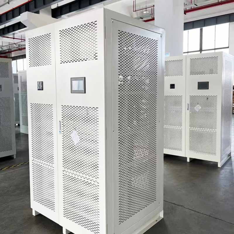
3phase-50KVA(input 380V±20% Output 380V±2%)
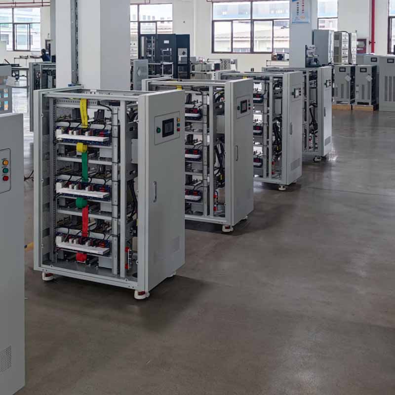
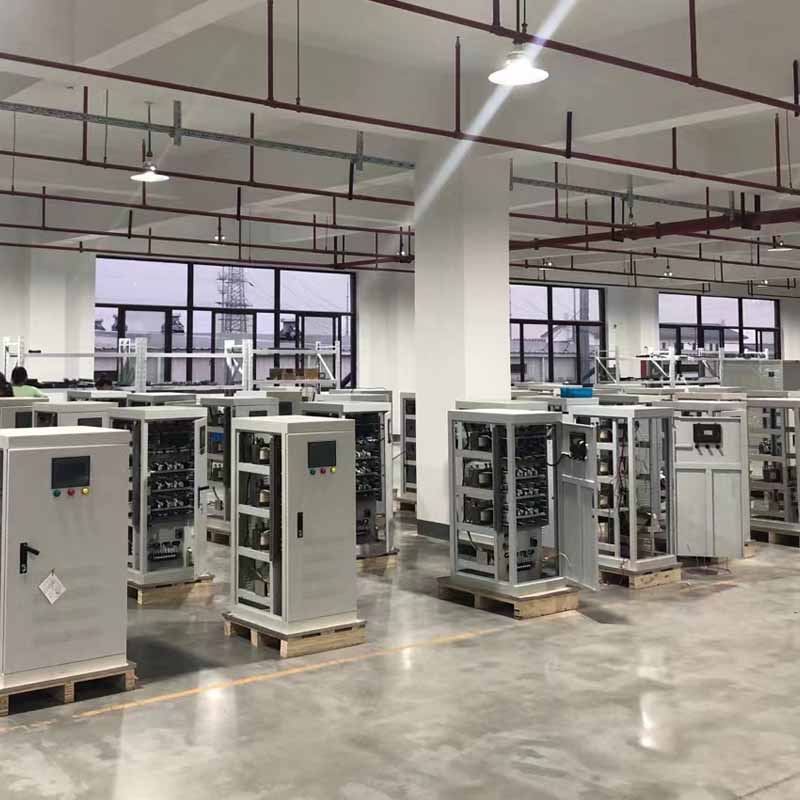
…
Medical imaging equipment CT field use stabilizer
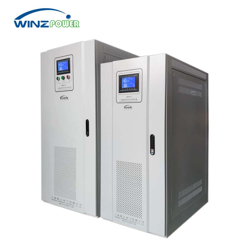
SBW Servo Motor Voltage Stabilizer
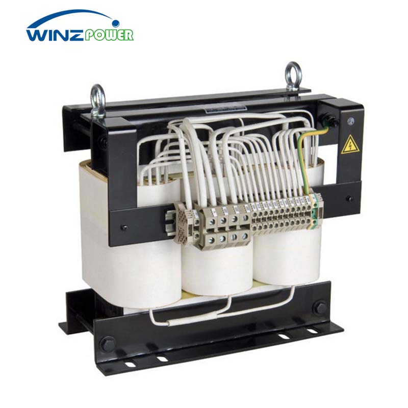
Three-phase Dry-type Isolation Transformer
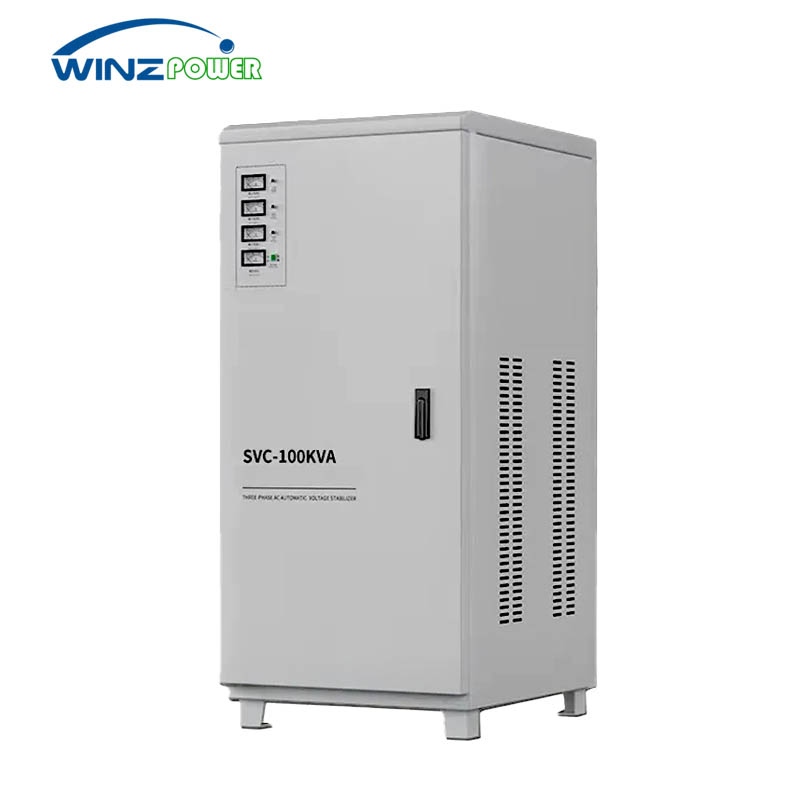
SVC Servo Motor Voltage Stabilizer
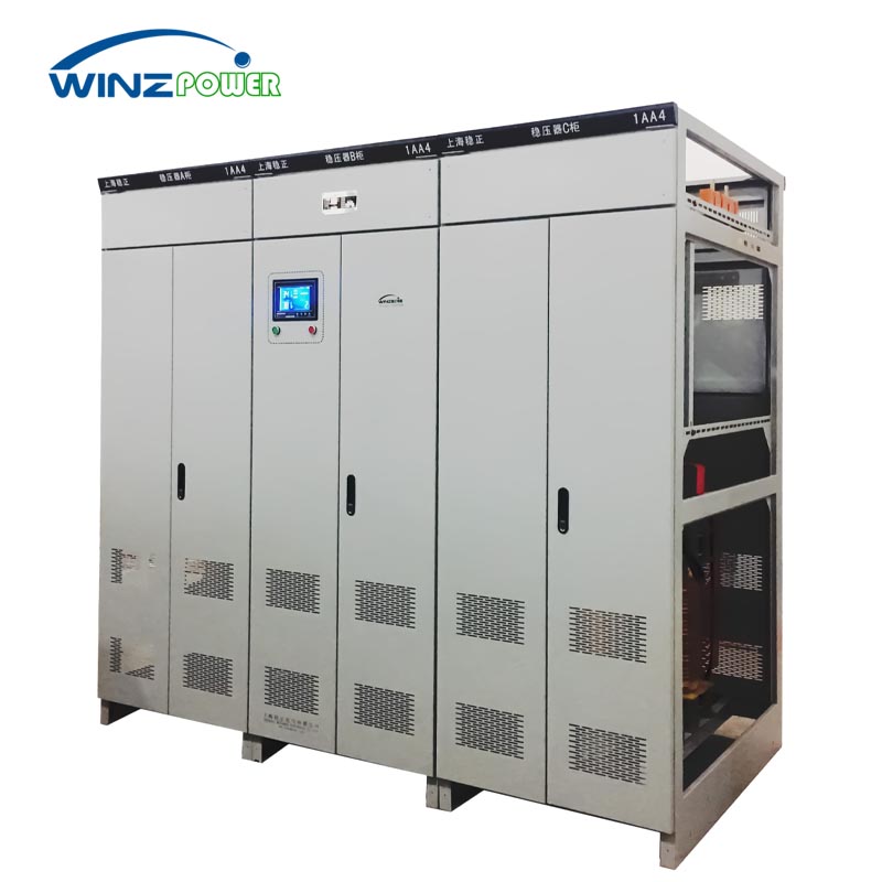
Three Phase Split-phase Automatic Voltage Stabilizer
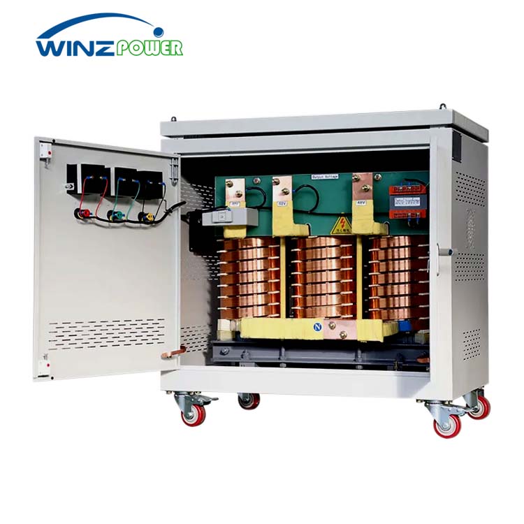
High-Current Dry Transformers
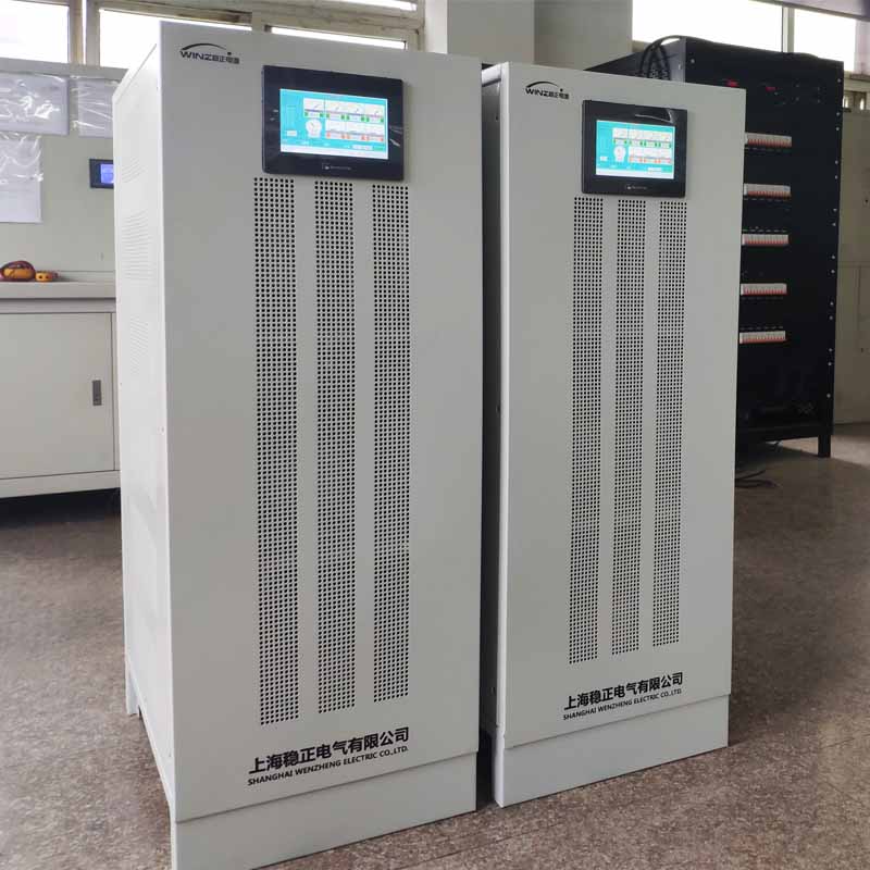
Static Non-contact SCR Voltage Regulator
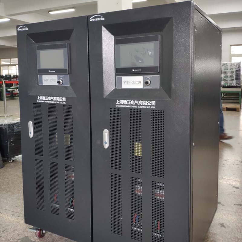
AC Variable Frequency Power Supply
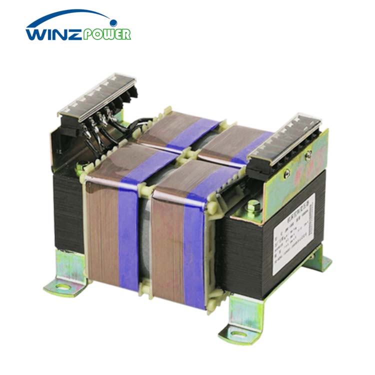
Low voltage control transformer

