
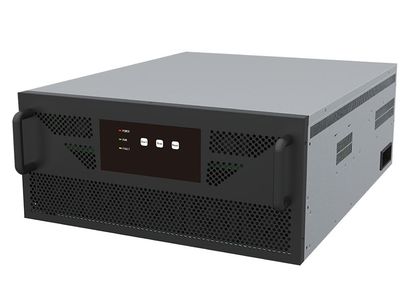


Active Harmonic Filter AHF
AHF( Active Harmonic Filter)
AHF is an active harmonic filter used in power grid systems. AHF eliminates harmonic currents caused by nonlinear loads in the power grid bus and improves the power quality in the power grid and cover the 2-50th harmonic compensation to meet the IEEE 519 standard.AHF runs in parallel in the power grid bus. Compared with LC series resonant passive harmonic filters, it has the advantages of fast speed, high efficiency, small size and low cost. It is currently the most ideal harmonic filtering device for power grid.
• Item NO: AHF
• OEM & ODM Service: Available
• Order(MOQ):1
• Payment:T/T,LC
Product Introduction
According to the requirements of the IEEE 519 standard, the total harmonic distortion rate (THD) must be less than 5%; use AHF to cover the 2-50th harmonic compensation to meet the IEEE 519 standard.
The AHF uses an external Transformer CT to detect the current or load current in real time. The AHF based on 3-level topology .The DSP+FPGA controller extracts the base sine wave current and each harmonic current of the load through the fast Fourier transform, and obtains active, reactive, and negative sequence data through the dq rotating coordinates. Then, the IGBT power converter generates a compensated current with same amplitude of the harmonic wave, but reverse polarity(harmonic, reactive, unbalanced), and compensated current is injected into the grid to achieve the power quality improvement function on the power grid side to eliminate the harmonic waves in the system.
AHF control principle diagram

AHF system topology (NPC three-level architecture)

AHF operation principle diagram

List of AHF Technical Parameters
|
Technical Data and Specifications |
|||
|
Rated Voltage(V) |
400V |
480V |
690V |
|
Rated (Capacity)(A) |
30A 50A 75A 100A 150A |
30A 50A 75A 100A 150A |
100A 150A |
|
Operating Frequency |
50/60Hz±10%(45~66Hz) |
||
|
Circuit Topology |
Three-level NPC |
||
|
Compensation Mode |
Harmonic compensation, Reactive compensation, three-phase load unbalance compensation |
||
|
Harmonic filter capability |
Better than 95% at rated load |
||
|
Filter range |
2nd~51st odd order harmonics (Selective or Full compensation) |
||
|
CT installation position |
Grid/load side |
||
|
CT installation mode |
Open loop or closed loop (open loop is recommended for parallel operation) |
||
|
Wire system |
Three-phase Three-Wire / Three-phase Four-Wire |
||
|
Number of parallel machines |
≤20(One control panel can control up to 8 units) |
||
|
Redundancy |
Any AHF unit can operate independently |
||
|
Rated of Harmonic Reduction |
≥95% (For typical harmonic order distortions) |
||
|
Filtering Performance |
Filtering performance is typically THDi ≤ 5% at rated load (even under the most severe loads). |
||
|
Overload capacity |
It can run continuously at 110% of the rated current and run for 1 minute at 120% of the rated current |
||
|
Target Power Factor |
Adjustable from -1.0 to +1.0 |
||
|
3 Phase Load Balancing Effect |
≤5%, Mitigate negative and zero sequence |
||
|
Neutral Filtering Capacity |
3 times the rated filter current(in case of 4 wire device) |
||
|
Switching/control frequency |
20kHz |
||
|
Full capacity response time |
≤5ms |
||
|
Output current limit |
Automatically limited within 100% of rated capacity to output |
||
|
Control algorithm |
Intelligent FFT,Self-adaptive control algorithm |
||
|
Controller |
DSP+FPGA |
||
|
Protection |
Hardware protection(IGBT ERR), Software protection(OV OC OF OL…) |
||
|
Communication interface |
RS485 and CAN |
||
|
Human Machine Interface |
External 7-inch screen /No screen/1.8-inch screen/ (optional) |
||
|
Communication protocols |
The factory default supports Modbus remote communication protocol; the communication interface uses RS485 and CAN bus, and supports mobile phone APP (optional) operation. |
||
|
Noise |
<60db (<45db during low-speed operation) |
||
|
Installation method |
Module embedded(Rack),wall mounted, free landing |
||
|
Level of protection |
IP20 |
||
|
Cooling method |
Speed regulation intelligent air cooling PWM Fans |
||
|
Color |
RAL7035,RAL9005, Customized colors |
||
|
Ambient temperature |
-25~55℃ |
||
|
Relative humidity |
Maximum 95%, without condensation |
||
|
Mounting height above sea level |
≤3000 at rated capacity; appropriately reduce the capacity if it is > 3000(1% derating per 100m) |
||
|
Qualifications |
Test Report |
||
|
Implementation Standards |
IEEE 519 |
||
Harm of harmonics and causes(References: Fuji Electric)
There are lots of electrical devices that have nonlinear operating characteristics even when applied voltage is sinusoidal in nature, the current drawn by the device is non-sinusoidal in nature. These nonlinear devices used in power distribution circuits create nonlinear currents and which subsequently causes voltage distortions. These nonlinear currents and voltages have been generally referred to as harmonic currents and voltages. These harmonics if disregarded or undetected may cause harmonic resonant conditions, which could present system operating problems resulting in complaints from customers and reduced life of power equipment as well as degraded efficiency and performance. Harmonic currents and voltages can cause many unfavourable effects on the power system itself and the connected loads. Malfunctioning of electronic equipment, capacitor failure, transformer and neutral conductor overheating, excessive heating in rotating machinery are some of these effects.
how do AHF work?(References: Eaton)
Harmonics come from the nonlinear load. Active harmonic filters, also called harmonic correction units, are parallel devices that act like a noise cancellation system and inject equal and opposite frequencies to mitigate harmonics. The filters can also provide additional current to correct the power factor. So, what’s left coming from the source flowing back to the utility is only a nice, clean current that is in phase.
For example, if we run four 6-pulse variable frequency drives at the same time, we have a harmonic spectrum of 5th and 7th and 11th and 13th harmonics. The waveform will show a significant amount of harmonic current in the total harmonic distortion. When the active harmonic filter is turned on, it will inject equal and opposite harmonics to cancel what’s there. The waveform now will be clean and in phase. If we go back and look at the harmonic spectrum, the current distortion is very low.
Adding active harmonic filters can be a good harmonic solution for power systems. Though more costly than other options, if you have multiple drives running all the time and multiple drives as backup, harmonic filters would be a reliable way to capture any and all of the harmonics coming from the loads. However, one important thing to know from a system design standpoint is that your drive should have either a DC choke or an AC line reactor to minimize the harmonics coming out of the drives.
Active harmonic filters typically come in 50, 75, 100, 200 and 300 ampere units that you can parallel. Another benefit to using active harmonic filters is that you cannot overload them, because once they put out the maximum harmonic current and power factor correction that they can, they stop producing at that level—whether it’s 100 or 120 amperes, whatever the case may be.
Using active harmonic filters on your power system provides a system-level solution for internal and external harmonic protection.
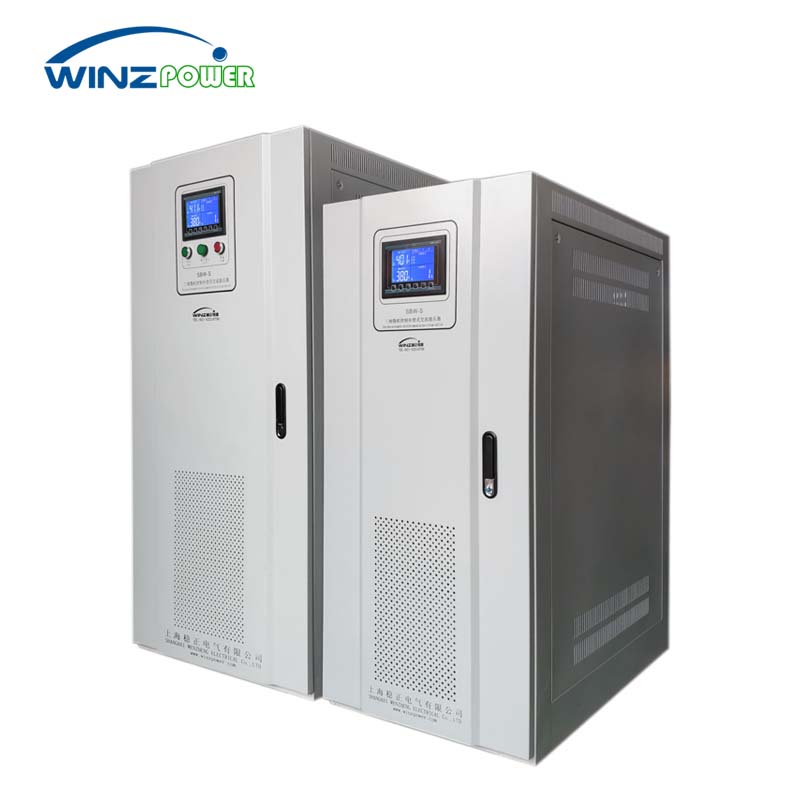
SBW Servo Motor Voltage Stabilizer
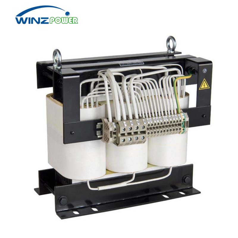
Three-phase Dry-type Isolation Transformer
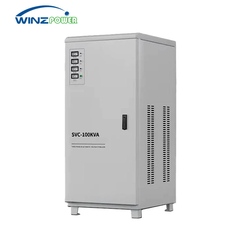
SVC Servo Motor Voltage Stabilizer
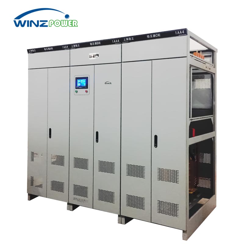
Three Phase Split-phase Automatic Voltage Stabilizer
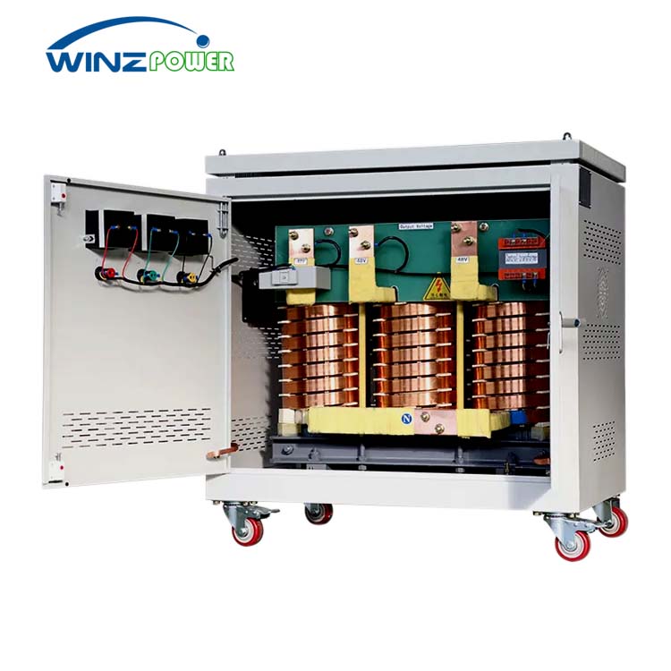
High-Current Dry Transformers
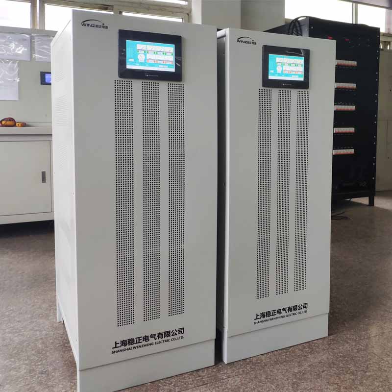
Static Non-contact SCR Voltage Regulator
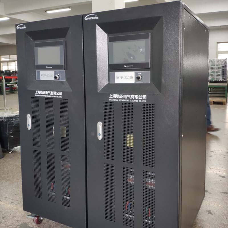
AC Variable Frequency Power Supply
Low voltage control transformer
