How to select the reactance rate of a low-voltage reactive power compensation system
To effectively suppress the amplification of the 5th and 7th harmonics, reactive power compensation systems with different reactance rates (5.5%, 6%, or 7%) are currently available on the market. Which system offers the best performance? How should one choose?
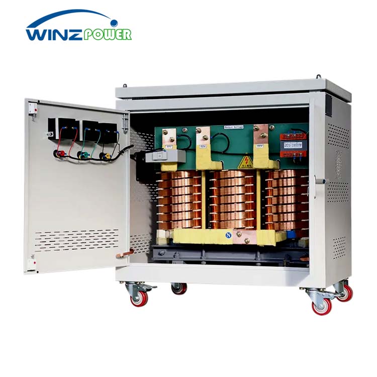
The Purpose of Connecting Capacitors in Series with Reactors
Due to the rapid development of power electronics technology and the maturity of semiconductor technology, industrial applications often utilize variable frequency drives for motors, controlled rectifiers, and intermittent control equipment that can adjust their output power according to the load size to achieve energy saving and consumption reduction. However, the current waveform of such loads is nonlinear and discontinuous during operation. Using pure capacitors as reactive power compensation in this situation will create the risk of parallel resonance.
To avoid parallel resonance between the pure capacitor and the system’s equivalent impedance, the capacitor is connected in series with a reactor. This makes the capacitor’s impedance in terms of system harmonic currents inductive, effectively avoiding the resonance point and preventing system resonance. Furthermore, connecting the capacitor in series with a reactor also reduces and suppresses inrush current.
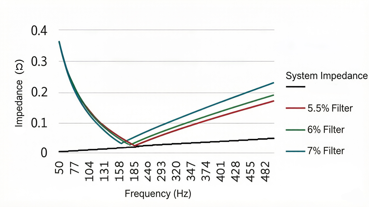
The primary purpose of reactive power compensation series reactors, besides compensating for system reactive power, is to avoid system parallel resonance points and prevent the risk of resonance. Whether using 5.5%, 6%, or 7% reactors, the main objective is to avoid amplifying the 5th and 7th harmonics. Therefore, the three reactance rates are functionally the same. However, it’s important to note that the harmonic absorption effect differs due to the different series reactance rates, and the voltage rise at the capacitor terminals also varies. Therefore, when using a 5.5% reactance rate, the rated current of the reactor should be carefully considered because its tuning frequency is closer to the 5th harmonic frequency than the other two rates, and the capacitor’s withstand voltage also needs to be increased accordingly. When using a 7% reactance rate, attention should be paid to the selection of the capacitor’s rated voltage because the voltage rise at the capacitor terminals is greater after connecting the reactor in series than with the other two rates. A comprehensive comparison of the three reactance rates is shown in Table 1.
| Reactance | 5.5% | 6% | 7% |
| function | Suppressing the 5th and 7th harmonics | Suppressing the 5th and 7th harmonics | Suppressing the 5th and 7th harmonics |
| 5th harmonic absorption effect | 35%~45% 25%~35% | 30%~40% | 25%~35% |
| Capacitor terminal voltage boost | 5.82% | 6.38% | 7.53% |
| Reactor current withstand | High | Medium | Low |
| Capacitor withstand voltage | High | Medium | Low |
When the system harmonic current is too large (generally greater than 100A), the tuned filter capacitor-reactor group may pose a safety hazard, and harmonic mitigation may be necessary.